Difference: BoardSupportPackageFlipper (1 vs. 19)
Revision 192023-12-31 - PeterSchmid
| Line: 1 to 1 | ||||||||
|---|---|---|---|---|---|---|---|---|
%DASHBOARD{ section="banner" | ||||||||
| Line: 10 to 10 | ||||||||
| The Flipper Zero has so many cool features, it is not easy to support all. At least in the beginning, I have to limit myself to a few features. | ||||||||
| Added: | ||||||||
| > > | This page is no longer updated regularly, the current documentation can be found at
GitHub | |||||||
 | ||||||||
Revision 182023-12-14 - PeterSchmid
| Line: 1 to 1 | ||||||||
|---|---|---|---|---|---|---|---|---|
%DASHBOARD{ section="banner" | ||||||||
| Line: 7 to 7 | ||||||||
| titlestyle="color:#F00000;"
}%
Intro
| ||||||||
| Changed: | ||||||||
| < < | TBD | |||||||
| > > | The Flipper Zero has so many cool features, it is not easy to support all. At least in the beginning, I have to limit myself to a few features. | |||||||
|
| ||||||||
| Line: 99 to 100 | ||||||||
| peripheral! ( flag -- ) set peripheral supply status, 0 switch off | ||||||||
| Added: | ||||||||
| > > | lcd-emit ( Char -- ) Emits a character (writes a character to the LCD display) lcd-emit? ( -- Flag ) LCD ready to get a character (I2C not busy) lcdpos! ( x y -- ) Set LCD cursor position, x (column) horizontal position, max. 127 y (row) vertical position (a line consists of 8 pixels), max. 7 lcdpos@ ( -- x y ) Get the current LCD cursor position lcdclr ( -- ) Clears the LCD display, sets the cursor to 0, 0 lcdfont ( u -- ) Select the font, u: 0 6x8, 1 8x8, 2 8X16 , 3 12X16 lcdcolumn! ( u -- ) Write a column (8 pixels) to the current position. Increment position. Bit 0 on top lcdcolumn@ ( -- u ) Read a column (8 pixels) from the current position | |||||||
Revision 172023-12-14 - PeterSchmid
| Line: 1 to 1 | ||||||||
|---|---|---|---|---|---|---|---|---|
%DASHBOARD{ section="banner" | ||||||||
| Line: 85 to 85 | ||||||||
| and get a message with length #2 from device to buffer at a SPImutex ( -- a ) get the SPI mutex address | ||||||||
| Added: | ||||||||
| > > | LIPOcharge@ ( -- u ) get LIPO charge [%] LIPOvoltage@ ( -- u ) get LIPO voltage [mV] LIPOcurrent@ ( -- n ) get LIPO current [mV] LIPOgauge@ ( u -- u ) get fuel gauge register LIPOgauge! ( u1 u2 -- ) set fuel gauge register u2 with data u1 LIPOcharger@ ( u -- u ) get charger register LIPOcharger! ( u1 u2 -- ) set charger register u2 with data u1 vibro@ ( -- flag ) get vibro state vibro! ( flag -- ) set vibro status, 0 switch off peripheral! ( flag -- ) set peripheral supply status, 0 switch off | |||||||
Revision 162023-12-14 - PeterSchmid
| Line: 1 to 1 | ||||||||
|---|---|---|---|---|---|---|---|---|
%DASHBOARD{ section="banner" | ||||||||
| Line: 25 to 25 | ||||||||
| wled! ( u -- ) set the W (LCD backlight) led wled@ ( -- u ) get the W (LCD backlight) led | ||||||||
| Changed: | ||||||||
| < < | switch1? ( -- ? ) get switch1 (BACK), closed=TRUE switch2? ( -- ? ) get switch2 (OK), closed=TRUE switch3? ( -- ? ) get switch3 (RIGHT), closed=TRUE | |||||||
| > > | switch1? ( -- ? ) get switch1 (BACK button), closed=TRUE switch2? ( -- ? ) get switch2 (OK button), closed=TRUE switch3? ( -- ? ) get switch3 (RIGHT button), closed=TRUE | |||||||
| switch4? ( -- ? ) get switch4 (LEFT), closed=TRUE | ||||||||
| Changed: | ||||||||
| < < | switch5? ( -- ? ) get switch5 (UP), closed=TRUE switch6? ( -- ? ) get switch6 (DOWN), closed=TRUE | |||||||
| > > | switch5? ( -- ? ) get switch5 (UP button), closed=TRUE switch6? ( -- ? ) get switch6 (DOWN button), closed=TRUE button ( -- c ) wait for and fetch the pressed button (similar to the key word) char b BACK, o OK, r RIGHT, l LEFT, u UP, d DOWN button? ( -- ? ) Is there a button press? | |||||||
| dport! ( n -- ) set the digital output port (D0=bit0 .. D15=bit15). dport@ ( -- n ) get the digital input/output port (D0=bit0 .. D15=bit15). | ||||||||
Revision 152023-11-29 - PeterSchmid
| Line: 1 to 1 | ||||||||
|---|---|---|---|---|---|---|---|---|
%DASHBOARD{ section="banner" | ||||||||
| Line: 337 to 337 | ||||||||
| ; | ||||||||
| Added: | ||||||||
| > > | ||||||||
|
| ||||||||
Revision 142023-11-26 - PeterSchmid
| Line: 1 to 1 | ||||||||
|---|---|---|---|---|---|---|---|---|
%DASHBOARD{ section="banner" | ||||||||
| Line: 20 to 20 | ||||||||
|
Defaults: Digital port pins D0 to D4 are inputs with pull-up resistors.
| ||||||||
| Changed: | ||||||||
| < < | rgbled! ( rgb -- ) sets the RGB led ($ff0000 red, $00ff00 green, $0000ff blue) | |||||||
| > > | rgbled! ( rgb -- ) set the RGB led ($ff0000 red, $00ff00 green, $0000ff blue) rgbled@ ( -- rgb ) get the RGB led ($ff0000 red, $00ff00 green, $0000ff blue) wled! ( u -- ) set the W (LCD backlight) led wled@ ( -- u ) get the W (LCD backlight) led | |||||||
| switch1? ( -- ? ) get switch1 (BACK), closed=TRUE switch2? ( -- ? ) get switch2 (OK), closed=TRUE | ||||||||
Revision 132023-11-26 - PeterSchmid
| Line: 1 to 1 | ||||||||
|---|---|---|---|---|---|---|---|---|
%DASHBOARD{ section="banner" | ||||||||
| Line: 472 to 472 | ||||||||
Vibro and Speaker
| ||||||||
| Changed: | ||||||||
| < < |
| |||||||
| > > |
| |||||||
| ||||||||
Revision 122023-11-26 - PeterSchmid
| Line: 1 to 1 | ||||||||||
|---|---|---|---|---|---|---|---|---|---|---|
%DASHBOARD{ section="banner" | ||||||||||
| Line: 469 to 469 | ||||||||||
| ||||||||||
| Added: | ||||||||||
| > > | Vibro and Speaker
| |||||||||
NFC | ||||||||||
Revision 112023-11-25 - PeterSchmid
| Line: 1 to 1 | ||||||||
|---|---|---|---|---|---|---|---|---|
%DASHBOARD{ section="banner" | ||||||||
| Line: 448 to 448 | ||||||||
| ||||||||
| Deleted: | ||||||||
| < < | From u8g2_glue.c
#define ST756X_CMD_ON_OFF 0b10101110 /**< 0:0 Switch Display ON/OFF: last bit */
#define ST756X_CMD_SET_LINE 0b01000000 /**< 0:0 Set Start Line: last 6 bits  */
#define ST756X_CMD_SET_PAGE 0b10110000 /**< 0:0 Set Page address: last 4 bits */
#define ST756X_CMD_SET_COLUMN_MSB 0b00010000 /**< 0:0 Set Column MSB: last 4 bits */
#define ST756X_CMD_SET_COLUMN_LSB 0b00000000 /**< 0:0 Set Column LSB: last 4 bits */
#define ST756X_CMD_SEG_DIRECTION 0b10100000 /**< 0:0 Reverse scan direction of SEG: last bit */
#define ST756X_CMD_INVERSE_DISPLAY 0b10100110 /**< 0:0 Invert display: last bit */
#define ST756X_CMD_ALL_PIXEL_ON 0b10100100 /**< 0:0 Set all pixel on: last bit */
#define ST756X_CMD_BIAS_SELECT 0b10100010 /**< 0:0 Select 1/9(0) or 1/7(1) bias: last bit */
#define ST756X_CMD_R_M_W 0b11100000 /**< 0:0 Enter Read Modify Write mode: read+0, write+1 */
#define ST756X_CMD_END 0b11101110 /**< 0:0 Exit Read Modify Write mode */
#define ST756X_CMD_RESET 0b11100010 /**< 0:0 Software Reset */
#define ST756X_CMD_COM_DIRECTION 0b11000000 /**< 0:0 Com direction reverse: +0b1000 */
#define ST756X_CMD_POWER_CONTROL 0b00101000 /**< 0:0 Power control: last 3 bits VB:VR:VF */
#define ST756X_CMD_REGULATION_RATIO 0b00100000 /**< 0:0 Regulation resistor ration: last 3bits */
#define ST756X_CMD_SET_EV 0b10000001 /**< 0:0 Set electronic volume: 5 bits in next byte */
#define ST756X_CMD_SET_BOOSTER \
    0b11111000 /**< 0:0 Set Booster level, 4X(0) or 5X(1): last bit in next byte */
#define ST756X_CMD_NOP 0b11100011 /**< 0:0 No operation */
| |||||||
microSD Adapter (SD Drive) | ||||||||
| Line: 484 to 461 | ||||||||
LIPO Charger, Fuel Gauge | ||||||||
| Changed: | ||||||||
| < < |
| |||||||
| > > |
| |||||||
| ||||||||
Revision 102023-11-25 - PeterSchmid
| Line: 1 to 1 | ||||||||
|---|---|---|---|---|---|---|---|---|
%DASHBOARD{ section="banner" | ||||||||
| Line: 438 to 438 | ||||||||
SPI LCD Display | ||||||||
| Changed: | ||||||||
| < < | Sitronix ST7567S (older devices ST7565R ?) | |||||||
| > > | Sitronix ST7567S | |||||||
| ||||||||
Revision 92023-11-20 - PeterSchmid
| Line: 1 to 1 | ||||||||||
|---|---|---|---|---|---|---|---|---|---|---|
%DASHBOARD{ section="banner" | ||||||||||
| Line: 438 to 438 | ||||||||||
SPI LCD Display | ||||||||||
| Added: | ||||||||||
| > > | Sitronix ST7567S (older devices ST7565R ?) | |||||||||
| ||||||||||
| Line: 446 to 448 | ||||||||||
| ||||||||||
| Added: | ||||||||||
| > > | From u8g2_glue.c
#define ST756X_CMD_ON_OFF 0b10101110 /**< 0:0 Switch Display ON/OFF: last bit */
#define ST756X_CMD_SET_LINE 0b01000000 /**< 0:0 Set Start Line: last 6 bits  */
#define ST756X_CMD_SET_PAGE 0b10110000 /**< 0:0 Set Page address: last 4 bits */
#define ST756X_CMD_SET_COLUMN_MSB 0b00010000 /**< 0:0 Set Column MSB: last 4 bits */
#define ST756X_CMD_SET_COLUMN_LSB 0b00000000 /**< 0:0 Set Column LSB: last 4 bits */
#define ST756X_CMD_SEG_DIRECTION 0b10100000 /**< 0:0 Reverse scan direction of SEG: last bit */
#define ST756X_CMD_INVERSE_DISPLAY 0b10100110 /**< 0:0 Invert display: last bit */
#define ST756X_CMD_ALL_PIXEL_ON 0b10100100 /**< 0:0 Set all pixel on: last bit */
#define ST756X_CMD_BIAS_SELECT 0b10100010 /**< 0:0 Select 1/9(0) or 1/7(1) bias: last bit */
#define ST756X_CMD_R_M_W 0b11100000 /**< 0:0 Enter Read Modify Write mode: read+0, write+1 */
#define ST756X_CMD_END 0b11101110 /**< 0:0 Exit Read Modify Write mode */
#define ST756X_CMD_RESET 0b11100010 /**< 0:0 Software Reset */
#define ST756X_CMD_COM_DIRECTION 0b11000000 /**< 0:0 Com direction reverse: +0b1000 */
#define ST756X_CMD_POWER_CONTROL 0b00101000 /**< 0:0 Power control: last 3 bits VB:VR:VF */
#define ST756X_CMD_REGULATION_RATIO 0b00100000 /**< 0:0 Regulation resistor ration: last 3bits */
#define ST756X_CMD_SET_EV 0b10000001 /**< 0:0 Set electronic volume: 5 bits in next byte */
#define ST756X_CMD_SET_BOOSTER \
    0b11111000 /**< 0:0 Set Booster level, 4X(0) or 5X(1): last bit in next byte */
#define ST756X_CMD_NOP 0b11100011 /**< 0:0 No operation */
| |||||||||
microSD Adapter (SD Drive) | ||||||||||
| Line: 468 to 493 | ||||||||||
| ||||||||||
| Added: | ||||||||||
| > > | NFCST25R3916 | |||||||||
Revision 82023-11-20 - PeterSchmid
Revision 72023-11-19 - PeterSchmid
| Line: 1 to 1 | ||||||||||
|---|---|---|---|---|---|---|---|---|---|---|
%DASHBOARD{ section="banner" | ||||||||||
| Line: 340 to 340 | ||||||||||
Pinouts | ||||||||||
| Added: | ||||||||||
| > > | Power
| |||||||||
GPIO Ports | ||||||||||
| Line: 439 to 447 | ||||||||||
| ||||||||||
| Changed: | ||||||||||
| < < |
| |||||||||
| > > |
| |||||||||
| ||||||||||
Revision 62023-11-13 - PeterSchmid
| Line: 1 to 1 | |||||||||||||
|---|---|---|---|---|---|---|---|---|---|---|---|---|---|
%DASHBOARD{ section="banner" | |||||||||||||
| Line: 8 to 8 | |||||||||||||
| }%
Intro
TBD | |||||||||||||
| Added: | |||||||||||||
| > > |
| ||||||||||||
| Line: 396 to 402 | |||||||||||||
| |||||||||||||
| Changed: | |||||||||||||
| < < | RGB LED | ||||||||||||
| > > | RGB LED, LCD Backlight LED | ||||||||||||
| |||||||||||||
| Changed: | |||||||||||||
| < < |
| ||||||||||||
| > > |
| ||||||||||||
| Changed: | |||||||||||||
| < < | PWM Driver Chip: TLC59731 | ||||||||||||
| > > | PWM Driver Chip: LP5562 | ||||||||||||
| Changed: | |||||||||||||
| < < | SPI is used for the timing. 4 SPI bits are one pulse position bit. fCLK(SDI) = 20 kHz to 600 kHz, the max. frequency for the SPI is therefore 2.4 MHz, I choosed 2 MHz. It takes about 30 us to set one RGB-LED. | ||||||||||||
| > > |
| ||||||||||||
UART VCP ST-LINK | |||||||||||||
| Line: 434 to 442 | |||||||||||||
| |||||||||||||
| Added: | |||||||||||||
| > > |
LIPO Charger, Fuel Gauge
| ||||||||||||
Revision 52023-11-12 - PeterSchmid
| Line: 1 to 1 | |||||||||||||||||||||||||||||
|---|---|---|---|---|---|---|---|---|---|---|---|---|---|---|---|---|---|---|---|---|---|---|---|---|---|---|---|---|---|
%DASHBOARD{ section="banner" | |||||||||||||||||||||||||||||
| Line: 214 to 214 | |||||||||||||||||||||||||||||
| Changed: | |||||||||||||||||||||||||||||
| < < | Only three port pins are supported so far. The 16 bit TIMER1 is used for the timebase, time resolution is 1 us (32 MHz SysClk divided by 32). The PWM scale is from 0 (0 % duty cycle) to 1000 (100 % duty cycle), this results in a PWM frequency of 1 kHz. If you need higher PWM frequencies, decrease the divider and/or the scale. | ||||||||||||||||||||||||||||
| > > | Only two port pins are supported so far. The 16 bit TIMER1 is used for the timebase, time resolution is 1 us (32 MHz SysClk divided by 32). The PWM scale is from 0 (0 % duty cycle) to 1000 (100 % duty cycle), this results in a PWM frequency of 1 kHz. If you need higher PWM frequencies, decrease the divider and/or the scale. | ||||||||||||||||||||||||||||
| Changed: | |||||||||||||||||||||||||||||
| < < | PWM port pins: D6 (TIM1CH1), D9 (TIM1CH2), D3 (TIM1CH3) | ||||||||||||||||||||||||||||
| > > | PWM port pins: D11 (TIM1CH1), D4 (TIM1CH2) | ||||||||||||||||||||||||||||
Simple test program to set brightness of a LED on pin D3 with a potentiometer on A0. Default PWM frequency is 1 kHz (prescaler set to 32). You can set the prescale with the word pwmprescale from 32 kHz (value 1) down to 0.5 Hz (64000).
| |||||||||||||||||||||||||||||
| Line: 254 to 254 | |||||||||||||||||||||||||||||
Output Compare | |||||||||||||||||||||||||||||
| Changed: | |||||||||||||||||||||||||||||
| < < | |||||||||||||||||||||||||||||
| > > | Only one port pin (D9) is supported so far. | ||||||||||||||||||||||||||||
: oc-toggle ( -- ) 5000000 ICOCperiod! \ 5 s period ICOCstart | |||||||||||||||||||||||||||||
| Changed: | |||||||||||||||||||||||||||||
| < < | 3 0 OCmod 1000000 0 OCstart \ toggle D0 after 1 s 3 1 OCmod 2000000 1 OCstart \ toggle D1 after 2 s 3 5 OCmod 3000000 5 OCstart \ toggle D5 after 3 s | ||||||||||||||||||||||||||||
| > > | 3 9 OCmod 1000000 0 OCstart \ toggle D9 after 1 s | ||||||||||||||||||||||||||||
| begin waitperiod cr .time | |||||||||||||||||||||||||||||
| Line: 347 to 345 | |||||||||||||||||||||||||||||
| |||||||||||||||||||||||||||||
| Changed: | |||||||||||||||||||||||||||||
| < < |
| ||||||||||||||||||||||||||||
| > > |
| ||||||||||||||||||||||||||||
| |||||||||||||||||||||||||||||
| Line: 386 to 384 | |||||||||||||||||||||||||||||
| Added: | |||||||||||||||||||||||||||||
| > > | |||||||||||||||||||||||||||||
Push Buttons | |||||||||||||||||||||||||||||
| Changed: | |||||||||||||||||||||||||||||
| < < |
| ||||||||||||||||||||||||||||
| > > |
| ||||||||||||||||||||||||||||
RGB LED | |||||||||||||||||||||||||||||
Revision 42023-11-11 - PeterSchmid
| Line: 1 to 1 | ||||||||||||||||||||||||||||||||||||||||||||||||||||||||||||||||||||||||||||
|---|---|---|---|---|---|---|---|---|---|---|---|---|---|---|---|---|---|---|---|---|---|---|---|---|---|---|---|---|---|---|---|---|---|---|---|---|---|---|---|---|---|---|---|---|---|---|---|---|---|---|---|---|---|---|---|---|---|---|---|---|---|---|---|---|---|---|---|---|---|---|---|---|---|---|---|---|
%DASHBOARD{ section="banner" | ||||||||||||||||||||||||||||||||||||||||||||||||||||||||||||||||||||||||||||
| Changed: | ||||||||||||||||||||||||||||||||||||||||||||||||||||||||||||||||||||||||||||
| < < | image="/twiki/pub/Cosmac/ForthSTM32WB/nucleo-header.jpg" | |||||||||||||||||||||||||||||||||||||||||||||||||||||||||||||||||||||||||||
| > > | image="/twiki/pub/MecrispCube/BoardSupportPackageFlipper/flipper-header.jpg" | |||||||||||||||||||||||||||||||||||||||||||||||||||||||||||||||||||||||||||
| title="Board Support Package for the Flipper Zero (STM32WB55 MCU)" titlestyle="color:#F00000;" }% | ||||||||||||||||||||||||||||||||||||||||||||||||||||||||||||||||||||||||||||
| Line: 365 to 365 | ||||||||||||||||||||||||||||||||||||||||||||||||||||||||||||||||||||||||||||
| ||||||||||||||||||||||||||||||||||||||||||||||||||||||||||||||||||||||||||||
| Added: | ||||||||||||||||||||||||||||||||||||||||||||||||||||||||||||||||||||||||||||
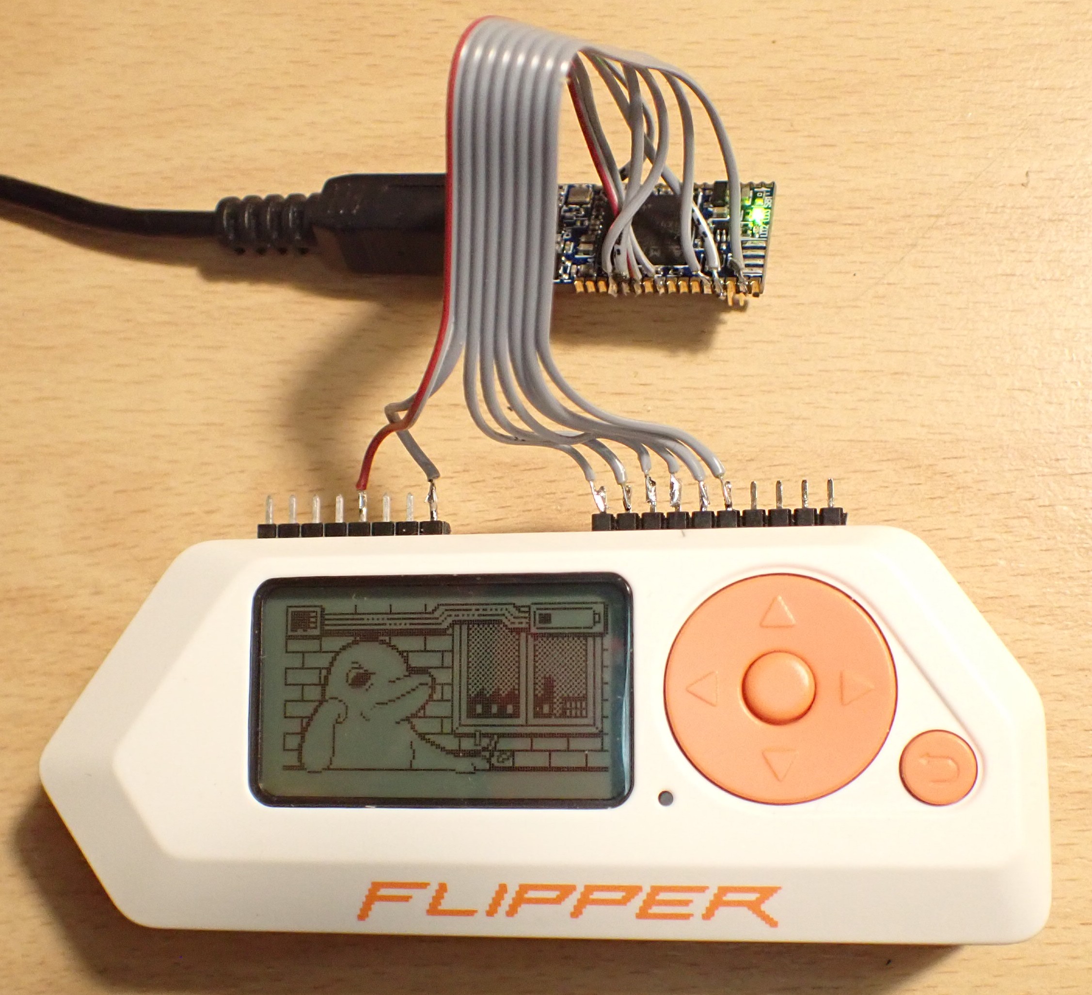
| > > | JTAG/SWD Adaptor | |||||||||||||||||||||||||||||||||||||||||||||||||||||||||||||||||||||||||||
| Added: | ||||||||||||||||||||||||||||||||||||||||||||||||||||||||||||||||||||||||||||
| > > |
| |||||||||||||||||||||||||||||||||||||||||||||||||||||||||||||||||||||||||||
Push Buttons | ||||||||||||||||||||||||||||||||||||||||||||||||||||||||||||||||||||||||||||
| Line: 426 to 445 | ||||||||||||||||||||||||||||||||||||||||||||||||||||||||||||||||||||||||||||
 This work by Peter Schmid is licensed under a Creative Commons Attribution-ShareAlike 4.0 International License.
| ||||||||||||||||||||||||||||||||||||||||||||||||||||||||||||||||||||||||||||
| Added: | ||||||||||||||||||||||||||||||||||||||||||||||||||||||||||||||||||||||||||||
| > > |
| |||||||||||||||||||||||||||||||||||||||||||||||||||||||||||||||||||||||||||
Revision 32023-10-29 - PeterSchmid
| Line: 1 to 1 | |||||||||||||||||||||||||||||||||||||||||||||||||||
|---|---|---|---|---|---|---|---|---|---|---|---|---|---|---|---|---|---|---|---|---|---|---|---|---|---|---|---|---|---|---|---|---|---|---|---|---|---|---|---|---|---|---|---|---|---|---|---|---|---|---|---|
%DASHBOARD{ section="banner" | |||||||||||||||||||||||||||||||||||||||||||||||||||
| Line: 370 to 370 | |||||||||||||||||||||||||||||||||||||||||||||||||||
Push Buttons
| |||||||||||||||||||||||||||||||||||||||||||||||||||
| Changed: | |||||||||||||||||||||||||||||||||||||||||||||||||||
| < < |
| ||||||||||||||||||||||||||||||||||||||||||||||||||
| > > |
| ||||||||||||||||||||||||||||||||||||||||||||||||||
RGB LED | |||||||||||||||||||||||||||||||||||||||||||||||||||
| Changed: | |||||||||||||||||||||||||||||||||||||||||||||||||||
| < < |
| ||||||||||||||||||||||||||||||||||||||||||||||||||
| > > |
| ||||||||||||||||||||||||||||||||||||||||||||||||||
| |||||||||||||||||||||||||||||||||||||||||||||||||||
| Line: 396 to 396 | |||||||||||||||||||||||||||||||||||||||||||||||||||
| |||||||||||||||||||||||||||||||||||||||||||||||||||
| Changed: | |||||||||||||||||||||||||||||||||||||||||||||||||||
| < < | SPI OLED Display
| ||||||||||||||||||||||||||||||||||||||||||||||||||
| > > | SPI LCD Display | ||||||||||||||||||||||||||||||||||||||||||||||||||
| Changed: | |||||||||||||||||||||||||||||||||||||||||||||||||||
| < < | |||||||||||||||||||||||||||||||||||||||||||||||||||
| > > |
| ||||||||||||||||||||||||||||||||||||||||||||||||||
microSD Adapter (SD Drive) | |||||||||||||||||||||||||||||||||||||||||||||||||||
| Changed: | |||||||||||||||||||||||||||||||||||||||||||||||||||
| < < |
| ||||||||||||||||||||||||||||||||||||||||||||||||||
| > > |
| ||||||||||||||||||||||||||||||||||||||||||||||||||
Revision 22023-10-29 - PeterSchmid
| Line: 1 to 1 | ||||||||||||||||||||||||||||||||||||||||||||||||||||||||||||||||||||||||
|---|---|---|---|---|---|---|---|---|---|---|---|---|---|---|---|---|---|---|---|---|---|---|---|---|---|---|---|---|---|---|---|---|---|---|---|---|---|---|---|---|---|---|---|---|---|---|---|---|---|---|---|---|---|---|---|---|---|---|---|---|---|---|---|---|---|---|---|---|---|---|---|---|
%DASHBOARD{ section="banner" | ||||||||||||||||||||||||||||||||||||||||||||||||||||||||||||||||||||||||
| Line: 15 to 15 | ||||||||||||||||||||||||||||||||||||||||||||||||||||||||||||||||||||||||
| Changed: | ||||||||||||||||||||||||||||||||||||||||||||||||||||||||||||||||||||||||
| < < | Defaults: Digital port pins D0 to D7 are push pull outputs, D8 to D15 are inputs with pull-up resistors. | |||||||||||||||||||||||||||||||||||||||||||||||||||||||||||||||||||||||
| > > | Defaults: Digital port pins D0 to D4 are inputs with pull-up resistors. | |||||||||||||||||||||||||||||||||||||||||||||||||||||||||||||||||||||||
| Changed: | ||||||||||||||||||||||||||||||||||||||||||||||||||||||||||||||||||||||||
| < < | led1! ( ? -- ) set LED1 (blue) led2! ( ? -- ) set LED2 (green) led3! ( ? -- ) set LED3 (red) led1@ ( -- ? ) get LED1 (blue) led2@ ( -- ? ) get LED2 (green) led3@ ( -- ? ) get LED3 (red) switch1? ( -- ? ) get switch1, closed=TRUE switch2? ( -- ? ) get switch2, closed=TRUE switch3? ( -- ? ) get switch3, closed=TRUE | |||||||||||||||||||||||||||||||||||||||||||||||||||||||||||||||||||||||
| > > | rgbled! ( rgb -- ) sets the RGB led ($ff0000 red, $00ff00 green, $0000ff blue) switch1? ( -- ? ) get switch1 (BACK), closed=TRUE switch2? ( -- ? ) get switch2 (OK), closed=TRUE switch3? ( -- ? ) get switch3 (RIGHT), closed=TRUE switch4? ( -- ? ) get switch4 (LEFT), closed=TRUE switch5? ( -- ? ) get switch5 (UP), closed=TRUE switch6? ( -- ? ) get switch6 (DOWN), closed=TRUE | |||||||||||||||||||||||||||||||||||||||||||||||||||||||||||||||||||||||
| dport! ( n -- ) set the digital output port (D0=bit0 .. D15=bit15). dport@ ( -- n ) get the digital input/output port (D0=bit0 .. D15=bit15). | ||||||||||||||||||||||||||||||||||||||||||||||||||||||||||||||||||||||||
| Line: 38 to 36 | ||||||||||||||||||||||||||||||||||||||||||||||||||||||||||||||||||||||||
| EXTImod ( u a -- ) set for pin a (D2, D4, D7, D10) the EXTI mode u: 0 rising, 1 falling, 2 both edges, 3 none EXTIwait ( u a -- ) wait for EXTI interrupt on pin a (D2, D4, D7, D10), timeout u in [ms] | ||||||||||||||||||||||||||||||||||||||||||||||||||||||||||||||||||||||||
| Changed: | ||||||||||||||||||||||||||||||||||||||||||||||||||||||||||||||||||||||||
| < < | pwmpin! ( u a -- ) set the digital output port pin a (D3=3, D6=6, D9=9) to a PWM value u (0..1000). Default frequency is 1 kHz, TIMER1 | |||||||||||||||||||||||||||||||||||||||||||||||||||||||||||||||||||||||
| > > | pwmpin! ( u a -- ) set the digital output port pin a (D4=4, D11=11) to a PWM value u (0..1000). Default frequency is 1 kHz, TIMER1 | |||||||||||||||||||||||||||||||||||||||||||||||||||||||||||||||||||||||
| pwmprescale ( u -- ) Set the PWM prescale for TIMER1. 32 kHz / prescale, default 32 -> PWM frequency 1 kHz ICOCprescale ( u -- ) set the input capture / output compare prescale for TIMER2. default 32 -> 32 MHz / 32 = 1 MHz, timer resolution 1 us | ||||||||||||||||||||||||||||||||||||||||||||||||||||||||||||||||||||||||
| Line: 61 to 59 | ||||||||||||||||||||||||||||||||||||||||||||||||||||||||||||||||||||||||
| OCwait ( a -- ) wait for the end of output capture on pin a ICwait ( u -- u ) wait for the end of input capture with timeout u, returns counter u | ||||||||||||||||||||||||||||||||||||||||||||||||||||||||||||||||||||||||
| Changed: | ||||||||||||||||||||||||||||||||||||||||||||||||||||||||||||||||||||||||
| < < | apin@ ( a -- u ) get the analog input port pin (A0 .. A5). Returns a 12 bit value (0..4095) | |||||||||||||||||||||||||||||||||||||||||||||||||||||||||||||||||||||||
| > > | apin@ ( a -- u ) get the analog input port pin (A0 .. A2). Returns a 12 bit value (0..4095) | |||||||||||||||||||||||||||||||||||||||||||||||||||||||||||||||||||||||
| vref@ ( -- u ) get the Vref voltage in mV (rather the VDDA) vbat@ ( -- u ) get the Vbat voltage in mV CPUtemp@ ( -- u ) get CPU temperature in degree Celsius | ||||||||||||||||||||||||||||||||||||||||||||||||||||||||||||||||||||||||
| Line: 349 to 347 | ||||||||||||||||||||||||||||||||||||||||||||||||||||||||||||||||||||||||
| ||||||||||||||||||||||||||||||||||||||||||||||||||||||||||||||||||||||||
| Changed: | ||||||||||||||||||||||||||||||||||||||||||||||||||||||||||||||||||||||||
| < < |
| |||||||||||||||||||||||||||||||||||||||||||||||||||||||||||||||||||||||
| > > |
| |||||||||||||||||||||||||||||||||||||||||||||||||||||||||||||||||||||||
| ||||||||||||||||||||||||||||||||||||||||||||||||||||||||||||||||||||||||
| Line: 362 to 360 | ||||||||||||||||||||||||||||||||||||||||||||||||||||||||||||||||||||||||
| ||||||||||||||||||||||||||||||||||||||||||||||||||||||||||||||||||||||||
| Changed: | ||||||||||||||||||||||||||||||||||||||||||||||||||||||||||||||||||||||||
| < < |
| |||||||||||||||||||||||||||||||||||||||||||||||||||||||||||||||||||||||
| > > |
| |||||||||||||||||||||||||||||||||||||||||||||||||||||||||||||||||||||||
| ||||||||||||||||||||||||||||||||||||||||||||||||||||||||||||||||||||||||
| Line: 377 to 375 | ||||||||||||||||||||||||||||||||||||||||||||||||||||||||||||||||||||||||
| ||||||||||||||||||||||||||||||||||||||||||||||||||||||||||||||||||||||||
| Changed: | ||||||||||||||||||||||||||||||||||||||||||||||||||||||||||||||||||||||||
| < < |
| |||||||||||||||||||||||||||||||||||||||||||||||||||||||||||||||||||||||
| > > |
| |||||||||||||||||||||||||||||||||||||||||||||||||||||||||||||||||||||||
| Changed: | ||||||||||||||||||||||||||||||||||||||||||||||||||||||||||||||||||||||||
| < < | LEDs | |||||||||||||||||||||||||||||||||||||||||||||||||||||||||||||||||||||||
| > > | RGB LED | |||||||||||||||||||||||||||||||||||||||||||||||||||||||||||||||||||||||
| Changed: | ||||||||||||||||||||||||||||||||||||||||||||||||||||||||||||||||||||||||
| < < |
| |||||||||||||||||||||||||||||||||||||||||||||||||||||||||||||||||||||||
| > > |
| |||||||||||||||||||||||||||||||||||||||||||||||||||||||||||||||||||||||
UART VCP ST-LINK | ||||||||||||||||||||||||||||||||||||||||||||||||||||||||||||||||||||||||
| Line: 393 to 396 | ||||||||||||||||||||||||||||||||||||||||||||||||||||||||||||||||||||||||
| ||||||||||||||||||||||||||||||||||||||||||||||||||||||||||||||||||||||||
| Changed: | ||||||||||||||||||||||||||||||||||||||||||||||||||||||||||||||||||||||||
| < < | Quad SPI for Flash
| |||||||||||||||||||||||||||||||||||||||||||||||||||||||||||||||||||||||
| > > | SPI OLED Display | |||||||||||||||||||||||||||||||||||||||||||||||||||||||||||||||||||||||
| Added: | ||||||||||||||||||||||||||||||||||||||||||||||||||||||||||||||||||||||||
| > > |
microSD Adapter (SD Drive)
| |||||||||||||||||||||||||||||||||||||||||||||||||||||||||||||||||||||||
Revision 12023-10-28 - PeterSchmid
| Line: 1 to 1 | |||||||||||||||||||||||||||||||||||||||||||||||||||||||||||||||||||||||||||||||||||||||||||||||||||||||||||||||||||||||||||||||||||||||||||||||||||||||||||||||||||||
|---|---|---|---|---|---|---|---|---|---|---|---|---|---|---|---|---|---|---|---|---|---|---|---|---|---|---|---|---|---|---|---|---|---|---|---|---|---|---|---|---|---|---|---|---|---|---|---|---|---|---|---|---|---|---|---|---|---|---|---|---|---|---|---|---|---|---|---|---|---|---|---|---|---|---|---|---|---|---|---|---|---|---|---|---|---|---|---|---|---|---|---|---|---|---|---|---|---|---|---|---|---|---|---|---|---|---|---|---|---|---|---|---|---|---|---|---|---|---|---|---|---|---|---|---|---|---|---|---|---|---|---|---|---|---|---|---|---|---|---|---|---|---|---|---|---|---|---|---|---|---|---|---|---|---|---|---|---|---|---|---|---|---|---|---|---|
| Added: | |||||||||||||||||||||||||||||||||||||||||||||||||||||||||||||||||||||||||||||||||||||||||||||||||||||||||||||||||||||||||||||||||||||||||||||||||||||||||||||||||||||
| > > |
Board Support Package for the Flipper Zero (STM32WB55 MCU)
Intro
TBD
Board Support WordsDefaults: Digital port pins D0 to D7 are push pull outputs, D8 to D15 are inputs with pull-up resistors.
led1!        ( ? -- )    set LED1 (blue)
led2!        ( ? -- )    set LED2 (green)
led3!        ( ? -- )    set LED3 (red)
led1@        ( -- ? )    get LED1 (blue)
led2@        ( -- ? )    get LED2 (green)
led3@        ( -- ? )    get LED3 (red)

switch1?     ( -- ? )    get switch1, closed=TRUE
switch2?     ( -- ? )    get switch2, closed=TRUE
switch3?     ( -- ? )    get switch3, closed=TRUE

dport!       ( n -- )    set the digital output port (D0=bit0 .. D15=bit15).
dport@       ( -- n )    get the digital input/output port (D0=bit0 .. D15=bit15).
dpin!        ( n a -- )  set the digital output port pin (D0=0 .. D15=15)
dpin@        ( a -- n )  get the digital input/output port pin
dmod         ( u a -- )  set the pin mode: 0 in, 1 in pull-up, 2 in pull-down, 3 out push pull, 4 out open drain,
                                            5 out push pull PWM, 6 input capture, 7 output compare, 8 I2C

EXTImod      ( u a -- )  set for pin a (D2, D4, D7, D10) the EXTI mode u: 0 rising, 1 falling, 2 both edges, 3 none
EXTIwait     ( u a -- )  wait for EXTI interrupt on pin a (D2, D4, D7, D10), timeout u in [ms]

pwmpin!      ( u a -- )  set the digital output port pin a (D3=3, D6=6, D9=9) to a PWM value u (0..1000). Default frequency is 1 kHz, TIMER1
pwmprescale  ( u --  )   Set the PWM prescale for TIMER1. 32 kHz / prescale, default 32 -> PWM frequency 1 kHz

ICOCprescale ( u -- )    set the input capture / output compare prescale for TIMER2. default 32 -> 32 MHz / 32 = 1 MHz, timer resolution 1 us
ICOCperiod!  ( u -- )    set the input capture / output compare (TIMER2) period. default $FFFFFFFF (4'294'967'295).
                         When the up counter reaches the period, the counter is set to 0.
                         For prescale 32 the maximum time is about 1 h 11 m
ICOCcount!   ( -- u )    set the input capture / output compare counter for TIMER2
ICOCcount@   ( u -- )    get the input capture / output compare counter for TIMER2
ICOCstart    ( -- )      start the ICOC period
ICOCstop     ( -- )      stop the ICOC period
OCmod        ( u a -- )  set for pin a (D0, D1, D5) the Output Compare mode u: 0 frozen, 1 active level on match, 2 inactive level on match,
                            3 toggle on match, 4 forced active, 5 forced inactive

OCstart      ( u a -- )  start the output compare mode for pin a with pulse u
OCstop       ( a -- )    stop output compare for pin a
ICstart      ( u -- )    start input capture u: 0 rising edge, 1 falling edge, 2 both edges
ICstop       ( -- )      stop input capture

waitperiod   ( -- )      wait for the end of the TIMER2 period
OCwait       ( a -- )    wait for the end of output capture on pin a
ICwait       ( u -- u )  wait for the end of input capture with timeout u, returns counter u

apin@        ( a -- u )  get the analog input port pin (A0 .. A5). Returns a 12 bit value (0..4095)
vref@        ( -- u )    get the Vref voltage in mV (rather the VDDA)
vbat@        ( -- u )    get the Vbat voltage in mV
CPUtemp@     ( -- u )    get CPU temperature in degree Celsius

I2Cput       ( a # u -- )     put a message with length u (count in bytes) from buffer at a to the I2C slave device u
I2Cget       ( a # u -- )     get a message with length u from I2C slave device to buffer at a
I2Cputget    ( a #1 #2 u -- ) put a message with length #1 from buffer at a to the I2C slave device u
                              and get a message with length #2 from device to buffer at a

SPIget       ( a # -- )       get a message with length # from SPI slave device to buffer at a
SPIput       ( a # -- )       put a message with length # from buffer at a to the SPI slave device
SPIputget    ( a #1 #2 -- )   put a message with length #1 from buffer at a to the SPI slave device
                              and get a message with length #2 from device to buffer at a
SPImutex     ( -- a )         get the SPI mutex address
Using the Digital Port Pins (Input and Output)This example is very similar to the McForth#Knight_Rider program.dport! and dport@ set and get all 16 digital pins (D0 to D15) at once. You have to press the SW1 push button til D0 is set to cancel the operation.
3 0 dmod   \ set D0 to Output
3 1 dmod   \ set D1 to Output
3 2 dmod   \ set D2 to Output
3 3 dmod   \ set D3 to Output
3 4 dmod   \ set D4 to Output
3 5 dmod   \ set D5 to Output
3 6 dmod   \ set D6 to Output
3 7 dmod   \ set D7 to Output
Using the ADC (Analog Input Pins)apin@ ( a -- u ) returns the ADC value (12 bit, 0 .. 4095) from one of the analog pins A0 to A5 (0 .. 5). Here I use the A0 to control the delay.
left or right word takes about 125 us, the knightrider loop about 50 us (no osDelay). Pretty fast for my opinion.
CH1 yellow: D0 pinCH2 blue: D1 pin 
Using the PWM (Analog Output Pins)Only three port pins are supported so far. The 16 bit TIMER1 is used for the timebase, time resolution is 1 us (32 MHz SysClk divided by 32). The PWM scale is from 0 (0 % duty cycle) to 1000 (100 % duty cycle), this results in a PWM frequency of 1 kHz. If you need higher PWM frequencies, decrease the divider and/or the scale. PWM port pins: D6 (TIM1CH1), D9 (TIM1CH2), D3 (TIM1CH3) Simple test program to set brightness of a LED on pin D3 with a potentiometer on A0. Default PWM frequency is 1 kHz (prescaler set to 32). You can set the prescale with the wordpwmprescale from 32 kHz (value 1) down to 0.5 Hz (64000).
5 3 dmod   \ set D3 to PWM

: pwm ( -- )
  begin
    0 apin@  4 /  3 pwmpin!
    10 osDelay drop
    switch1?
  until
;
Using Input Capture and Output CompareTime BaseDefault timer resolution is 1 us. The 32 bit TIMER2 is used as time base for Input Capture / Output Compare. For a 5 s period 5'000'000 cycles are needed. All channels (input capture / output compare) use the same time base.
: period ( -- )
  5000000 ICOCperiod! \ 5 s period
  ICOCstart
  begin
     waitperiod
     cr .time
  key? until
  key drop
;
Output Compare
: oc-toggle ( -- )
  5000000 ICOCperiod! \ 5 s period
  ICOCstart
  3 0 OCmod  1000000 0 OCstart \ toggle D0 after 1 s
  3 1 OCmod  2000000 1 OCstart \ toggle D1 after 2 s
  3 5 OCmod  3000000 5 OCstart \ toggle D5 after 3 s
  begin
     waitperiod
     cr .time
  key? until
  key drop
;
When you abort (hit any key) the program, the timer still runs and controls the port pins. To stop the port pins:
0 OCstop 1 OCstop 5 OCstopOr change the prescale to make it faster or slower: 1 ICOCprescale Input CaptureThis sample program measures the time between the edges on port A2. if no event occurs within 2 seconds, "timeout" is issued. Hit any key to abort program.
: ic-test ( -- )
  6 2 dmod \ input capture on A2
  ICOCstart
  2 ICstart  \ both edges
  ICOCcount@ ( -- count )
  begin
    2000 \ 2 s timeout
    ICwait ( -- old-capture capture )
    cr
    dup 0= if
      ." timeout" drop
    else
      dup rot ( -- capture capture old-capture )
      - 1000 / . ." ms"
    then
  key? until
  key drop
  drop
  ICstop
;
PinoutsGPIO Ports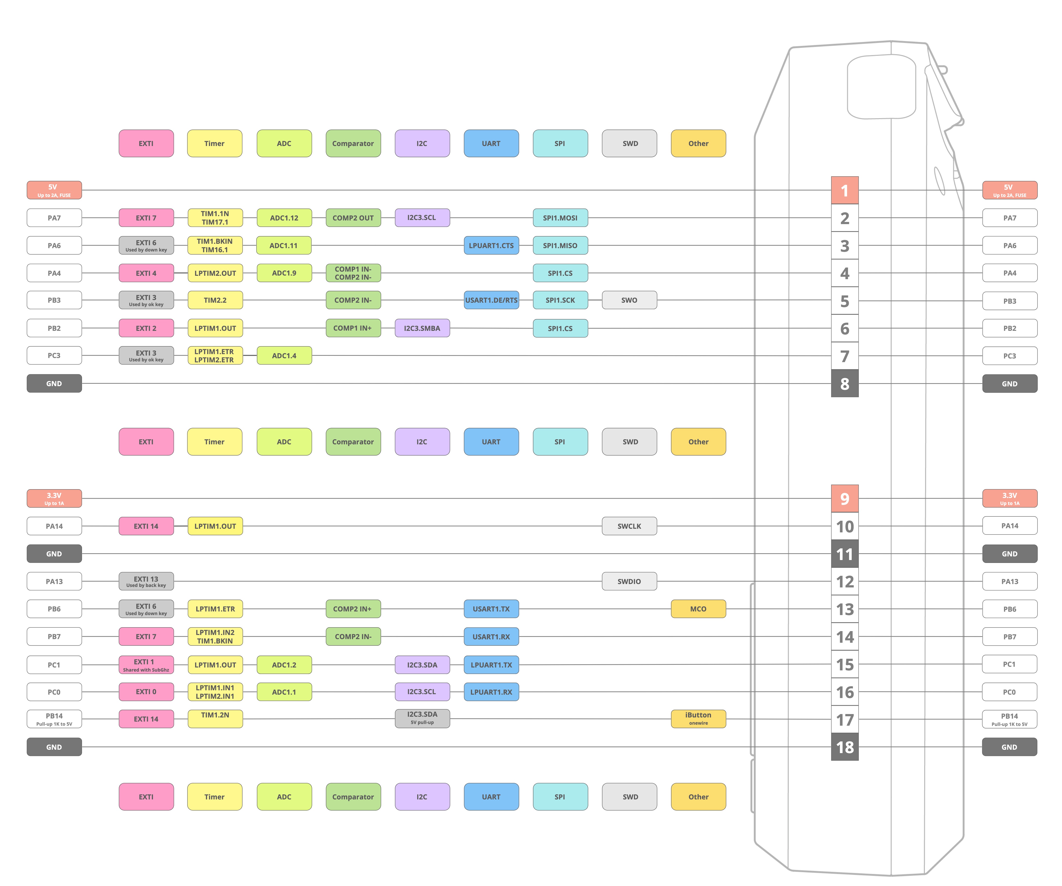
Push Buttons
LEDs
UART VCP ST-LINK
Quad SPI for Flash
This work by Peter Schmid is licensed under a Creative Commons Attribution-ShareAlike 4.0 International License.
| ||||||||||||||||||||||||||||||||||||||||||||||||||||||||||||||||||||||||||||||||||||||||||||||||||||||||||||||||||||||||||||||||||||||||||||||||||||||||||||||||||||
View topic | History: r19 < r18 < r17 < r16 | More topic actions...
Ideas, requests, problems regarding TWiki? Send feedback