How To Use
Single Pixel
The Adafruit Feather STM32F405 Board has its own Neopixel (GPIO PC0, D8) :
neopixel! ( rgb -- ) sets the neopixel RGB led ($ff0000 red, $00ff00 green, $0000ff blue)
On the
STM32WB Feather Development Board the
NeoPixel shares the LED D12 pin. It is easy to add an Adafruit pixel breakout board or a Flora Pixel at the top of the shield. The LED can be used concurrently.
- green: successfull USB enumeration
- blue: BLE connected
- flashing red: file write operation
- flashing yellow: file read operation
For the
STM32WB Nucleo Board I use D6 for the Neopixel
3 6 dmod           \ D6 output
$ff0000 neopixel!   \ red LED 100 % brightness
Neopixel Wing with 32 Pixels
NeoPixelWing uses the D6 as datapin for the Neopixels:
3 6 dmod                       \ D6 output
32 cells buffer: pixelbuffer    \ create buffer for the neopixels
$ff0000 pixelbuffer !            \ 1st Neopixel red
$00ff00 pixelbuffer 1 cells + !   \ 2nd Neopixel green
$0000ff pixelbuffer 2 cells + !    \ 3th Neopixel blue
$7f7f7f pixelbuffer 3 cells + !     \ 4th Neopixel white 50 %
pixelbuffer 4 neopixels

create pixels
$010000 , $020000 , $040000 , $080000 , $100000 , $200000 , $400000 , $800000 , \ 1st row red
$008000 , $004000 , $002000 , $001000 , $000800 , $000400 , $000200 , $000100 , \ 2nd row green
$000001 , $000002 , $000004 , $000008 , $000010 , $000020 , $000040 , $000080 , \ 3th row blue
$808080 , $404040 , $202020 , $101010 , $080808 , $040404 , $020202 , $010101 , \ 4th row white
pixels 32 neopixels
Implementation
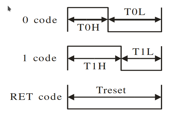
Timing
WS2812B Neopixel
| |
|
WS2812B |
SK6812 |
| T0H |
0 code, high voltage time |
0.4 us ±150 ns |
0.3 us ±150 ns |
| T1H |
1 code, high voltage time |
0.8 us ±150 ns |
0.6 us ±150 ns |
| T0L |
0 code, low voltage time |
0.85 us ±150 ns |
0.9 us ±150 ns |
| T1L |
1 code, low voltage time |
0.45 us ±150 ns |
0.6 us ±150 ns |
| RES |
low voltage time |
Above 50 us |
80 us |
- 1 bit takes 1.25 us (800 kHz), 24 bit take 30 us
- Timer resolution 0.25 us
- MSB first
- GRB
- 3 cycles for a wait loop
   lsls     r3, r3, #1   // set carry bit
   ittee    cs
   movwcs   r5, #T1H
   movtcs   r5, #T1L
   movwcc   r5, #T0H
   movtcc   r5, #T0L
6 cycles.
HTML Color 0xRRGGBB
F405
https://github.com/spyren/Mecrisp-Cube/blob/F405/Forth/cube/wings.s
Cycle = 1 / 168 MHz = 6 ns
0.4 us / 6 ns = 66.7 -> max. 66 cycles

.equ	T0H,		16	// 0.3 us
.equ	T1H,		40	// 0.8 us
.equ	T0L,		36	// 0.8 us
.equ	T1L,		12	// 0.3 us
WB55
Cycle = 1 / 32 MHz = 31.25 ns
0.4 us / 31.25 ns = 12.8 -> max 12 cycles


.equ	T0H,		4	// 0.4 us / (3 * 31.25 ns) = 4.27  -> 4
.equ	T1H,		8	// 0.8 us / (3 * 31.25 ns) = 8.53  -> 8
.equ	T0L,		5	// 0.85 us / (3 * 31.25 ns) = 9.07 -> 5 (4 turns less)
.equ	T1L,		1	// 0.45 us / (3 * 31.25 ns) = 4.53 -> 1 (4 turns less)

.equ	RESTIME,	533	// 50 us / (3 * 31.25 ns) = 533

//	Registers
.equ	GPIO_BSRR,	0x18	// GPIOx->BSRR bit set/reset


.global		BSP_neopixelDataTx
BSP_neopixelDataTx:
	push	{r4-r6, lr}
	lsl	r2, r2, #8		// r2 = rrggbb00
	mov	r3, r2			// r3 = rrggbb00
	bfc	r3, #16, #16		// r3 = 0000bb00
	rev16	r2, r2			// r2 = ggrr00bb
	bfc	r2, #0, #16		// r2 = ggrr0000
	add	r2, r2, r3		// r2 = ggrrbb00

	lsl	r3, r1, #16		// clear port pin for BSRR
	mov	r6, #24			// 24 bits

	// set DOUT pin low and wait reset time
	str	r3, [r0, #GPIO_BSRR]
	ldr	r4, =RESTIME
1:	subs	r4, r4, #1                                                 1
	bne	1b


                                                                         cycles
bit_loop:
	lsls	r2, r2, #1	// get the next bit -> set the carry bit   1
	ittee	cs                                                         1
	movcs	r4, #T1H                                                   1
	movcs	r5, #T1L                                                   1
	movcc	r4, #T0H                                                   1
	movcc	r5, #T0L                                                   1


	// set DOUT pin high
	str	r1, [r0, #GPIO_BSRR]                                       2
1:	subs	r4, r4, #1                                                 1
	bne	1b                                                         1 (2)

	// set DOUT pin low
	str	r3, [r0, #GPIO_BSRR]                                       2
2:	subs	r5, r5, #1                                                 1
	bne	2b                                                         1 (2)

	subs	r6, r6, #1                                                 1
	bne	bit_loop                                                   2

	pop	{r4-r6, pc}
Set/Reset Portpin
GPIO port bit set/reset register GPIOx_BSRR
- Address offset: 0x18, x = A..K, D8 = PC0
- bit0 .. bit15 bit set
- bit16 .. bit31 bit reset
#define GPIOC_BASE            (AHB1PERIPH_BASE + 0x0800UL)
#define AHB1PERIPH_BASE       (PERIPH_BASE + 0x00020000UL)
#define PERIPH_BASE           0x40000000UL /*!< Peripheral base address in the alias region                                */

GPIOC->BSRR


