Difference: BlueDCC (1 vs. 11)
Revision 112025-04-22 - PeterSchmid
| Line: 1 to 1 | ||||||||
|---|---|---|---|---|---|---|---|---|
BlueDCC Bluetooth Low Energy DCC | ||||||||
| Line: 8 to 8 | ||||||||
| * Battery operated (LiPol single cell) * Built in USB charger | ||||||||
| Changed: | ||||||||
| < < | * Up to 1 A | |||||||
| > > | * Up to 0.5 A | |||||||
| * Maximum DC adjustable from 6 to 15 V | ||||||||
| Changed: | ||||||||
| < < | * PWM from 25 Hz to 20 KHz | |||||||
| > > | * PWM from 25 Hz to 16 KHz | |||||||
| * BLE * Displays voltage and current | ||||||||
| Added: | ||||||||
| > > |  | |||||||
Controller | ||||||||
Revision 102025-04-08 - PeterSchmid
| Line: 1 to 1 | ||||||||
|---|---|---|---|---|---|---|---|---|
BlueDCC Bluetooth Low Energy DCC | ||||||||
| Line: 145 to 145 | ||||||||
| Added: | ||||||||
| > > | ||||||||
Kommerzielle BLE DCC | ||||||||
Revision 92025-04-08 - PeterSchmid
| Line: 1 to 1 | ||||||||
|---|---|---|---|---|---|---|---|---|
BlueDCC Bluetooth Low Energy DCC | ||||||||
| Line: 144 to 144 | ||||||||
| Added: | ||||||||
| > > | ||||||||
Kommerzielle BLE DCC | ||||||||
Revision 82025-01-18 - PeterSchmid
| Line: 1 to 1 | ||||||||
|---|---|---|---|---|---|---|---|---|
BlueDCC Bluetooth Low Energy DCC | ||||||||
| Added: | ||||||||
| > > | Pocket Power Pack 3P* Battery operated (LiPol single cell) * Built in USB charger * Up to 1 A * Maximum DC adjustable from 6 to 15 V * PWM from 25 Hz to 20 KHz * BLE * Displays voltage and currentControllerMotorentreiber
StrommessungDCDC AufwärtswandlerLiPo (3.3 bis 4.2 V) auf 12 V
LiPo Ladegerät
| |||||||
DCC-BLE Gateway | ||||||||
| Line: 92 to 127 | ||||||||
| Deleted: | ||||||||
| < < | Motorentreiber
StrommessungDCDC AufwärtswandlerLiPo (3.3 bis 4.2 V) auf 12 V
| |||||||
Elektronische Schwungmasse | ||||||||
Revision 72025-01-12 - PeterSchmid
| Line: 1 to 1 | ||||||||
|---|---|---|---|---|---|---|---|---|
BlueDCC Bluetooth Low Energy DCC | ||||||||
| Line: 92 to 92 | ||||||||
| Deleted: | ||||||||
| < < | BLE Test AppCLI: Laird Toolkit Serial (VSP)RaspiPWM auf BL652Jeder Output-Pin kann mit PWM betrieben werden.
| |||||||
Motorentreiber
| ||||||||
| Line: 197 to 149 | ||||||||
|
https://www.tcsdcc.com/product-page/6-pin-2x3-mini-connector-colored-wires | ||||||||
| Added: | ||||||||
| > > | BLE Test AppCLI: Laird Toolkit Serial (VSP)RaspiPWM auf BL652Jeder Output-Pin kann mit PWM betrieben werden.
| |||||||
--  | ||||||||
Revision 62025-01-10 - PeterSchmid
| Line: 1 to 1 | ||||||||
|---|---|---|---|---|---|---|---|---|
BlueDCC Bluetooth Low Energy DCC | ||||||||
| Line: 145 to 145 | ||||||||
| Changed: | ||||||||
| < < | ||||||||
| > > | ||||||||
Strommessung | ||||||||
Revision 52025-01-09 - PeterSchmid
| Line: 1 to 1 | ||||||||
|---|---|---|---|---|---|---|---|---|
BlueDCC Bluetooth Low Energy DCC | ||||||||
| Line: 144 to 144 | ||||||||
| Added: | ||||||||
| > > |
StrommessungDCDC AufwärtswandlerLiPo (3.3 bis 4.2 V) auf 12 V
| |||||||
Elektronische Schwungmasse | ||||||||
| Line: 179 to 195 | ||||||||
| ||||||||
| Added: | ||||||||
| > > | https://www.tcsdcc.com/product-page/6-pin-2x3-mini-connector-colored-wires | |||||||
|
-- | ||||||||
Revision 42018-12-27 - PeterSchmid
| Line: 1 to 1 | ||||||||
|---|---|---|---|---|---|---|---|---|
BlueDCC Bluetooth Low Energy DCC | ||||||||
| Line: 182 to 182 | ||||||||
|
-- | ||||||||
| Changed: | ||||||||
| < < | Comments | |||||||
| > > |
 This work by Peter Schmid is licensed under a Creative Commons Attribution-ShareAlike 4.0 International License. | |||||||
| Deleted: | ||||||||
| < < | ||||||||
| ||||||||
Revision 32018-12-14 - PeterSchmid
| Line: 1 to 1 | ||||||||
|---|---|---|---|---|---|---|---|---|
BlueDCC Bluetooth Low Energy DCC | ||||||||
| Line: 80 to 80 | ||||||||
| CurrentKeeper Installation | ||||||||
| Changed: | ||||||||
| < < | These decoders are equipped with a 2-pin socket specifically for the CurrentKeeper. You | |||||||
| > > | These decoders are equipped with a 2-pin socket specifically for the CurrentKeeper. | |||||||
|
Allgemeine Schnittstellenbeschreibung:
https://www.opendcc.de/info/decoder/schnittstellen.html | ||||||||
| Added: | ||||||||
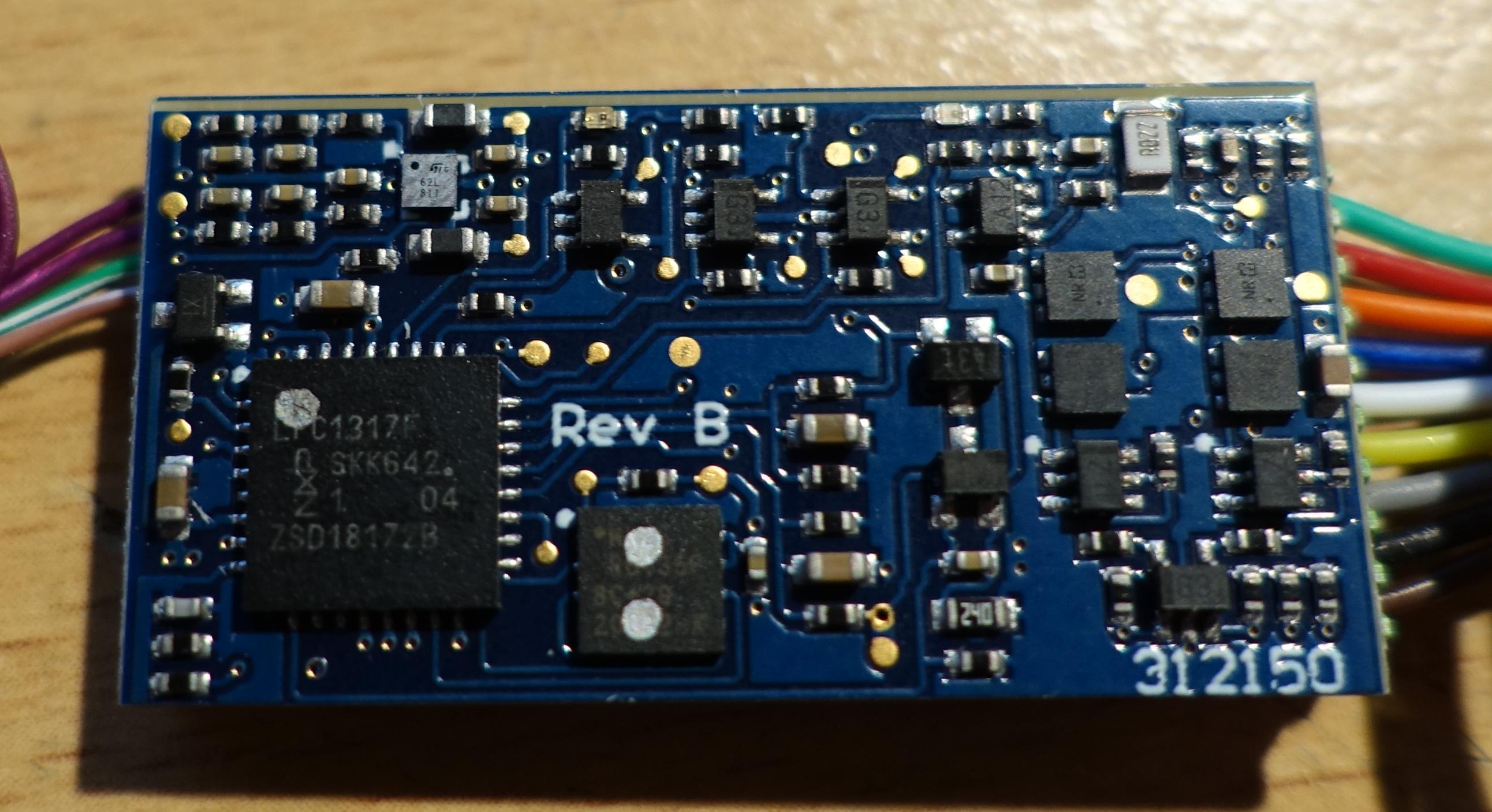
| > > | MCU LPC1317FHN33, https://www.nxp.com/docs/en/data-sheet/LPC1315_16_17_45_46_47.pdf
| |||||||
BLE Test AppCLI: Laird Toolkit Serial (VSP) | ||||||||
| Line: 178 to 185 | ||||||||
Comments | ||||||||
| Added: | ||||||||
| > > |
| |||||||
Revision 22018-10-28 - PeterSchmid
| Line: 1 to 1 | ||||||||
|---|---|---|---|---|---|---|---|---|
BlueDCC Bluetooth Low Energy DCC | ||||||||
| Line: 26 to 26 | ||||||||
| ||||||||
| Changed: | ||||||||
| < < |
| |||||||
| > > |
| |||||||
| Die gleiche Elektronik könnte auch für einen BLE-Decoder verwendet werden. Statt die Bridge für einen Booster zu verwenden, könnte man mit der Bridge direkt den Motor ansteuern. Für weitere Funktionen hättte der BL652 genügend Ports. | ||||||||
| Line: 51 to 51 | ||||||||
| Dieser eingeprägte Strom wird von einem Sensor erfaßt, dieser wandelt das Signal wieder in ein reguläres RS232-Signal um, welches dann von der Zentrale ausgewertet wird. Laut NMRA dürfen die Taktraten um +/- 2% abweichen. Ich halte das für gewagt: sollten Sender und Empfänger die Toleranz in die entgegengesetzte Richtung ausnutzen, so ergibt sich ein max. Offset des Samplezeitpunkts von 8*4% = 32%. Typischerweise wird beim Startbit in der Mitte begonnen, d.h. gegen Ende des Bytes kommt man dem Rand des Bits gefährlich nahe, vor allem wenn man auch noch die Anstiegs-Abfallzeiten der Hardware mit in Kalkül ziehen muß. | ||||||||
| Added: | ||||||||
| > > | Digitrax TranspondingProprietäre Technologie von Digitrax. Die Präambel wird wird durch den Dekoder moduliert. Einzig Soundtraxx unterstütz auch noch diese Technologie. | |||||||
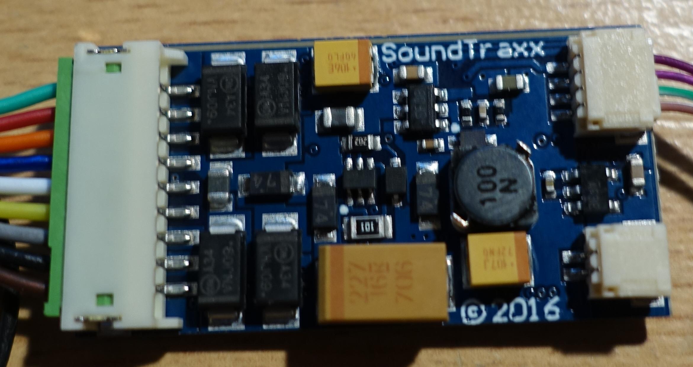
Sample Locomotive Decoder Soundtraxx TSU 2200Wiring Diagrams Tsunami2 and Econami Installation Guide 18 TSU 2200/ECO | ||||||||
Revision 12018-10-28 - PeterSchmid
| Line: 1 to 1 | ||||||||
|---|---|---|---|---|---|---|---|---|
| Added: | ||||||||
| > > |
BlueDCC Bluetooth Low Energy DCCDCC-BLE GatewayBLE-DCC Gateway
Bidirektionale KommunikationIst das überhaupt nötig? Es ist ja nur ein Dekoder angeschlossen und es kann davon ausgegangen werden, dass die Kommunikation klappt. Doch ein Zurücklesen von CVs wäre trotzdem schön.ACK CV read-backKurzzeitige Stromerhöhung um etwa 60 mA. Braucht eine Strommessung auf der Seite des Gateways. Strommessung wäre auch interessant für die Überwachung des Dekoders bzw. des Motors. Nur während der Programmierphase. https://dccwiki.com/Decoder_ProgrammingRailCom AKA DCC-BiDihttps://www.opendcc.de/info/railcom/railcom.htmlSample Locomotive Decoder Soundtraxx TSU 2200Wiring Diagrams Tsunami2 and Econami Installation Guide 18 TSU 2200/ECO Pin JST plug for easy installation in many DCC ready models. Wires are color-coded according to the NMRA Standard (where applicable): Power, Motor, Headlight, and Backup Light Wires:
BLE Test AppCLI: Laird Toolkit Serial (VSP)RaspiPWM auf BL652Jeder Output-Pin kann mit PWM betrieben werden.
MotorentreiberElektronische SchwungmasseU = 10 V I = 100 mA t = 100 ms R = U / I = 10 V / 100 mA = 100 Ohm C = t/100 = 1000 uF Open Source DCC, DokuKommerzielle BLE DCC
Lok-Dekoder mit BLE InterfaceThese systems work by installing a receiver board in the locomotive that acts as both a radio receiver and a miniature DCC command station/booster
Comments | |||||||
View topic | History: r11 < r10 < r9 < r8 | More topic actions...
Ideas, requests, problems regarding TWiki? Send feedback