Forth for the Membership Card
Intro
Computers are machines just like the marionette. They must be told exactly what to do, in specific language. And so we need a language which possesses two seemingly opposite traits:
On the one hand, it must be precise in its meaning to the computer, conveying all the information that the computer needs to know to perform the operation. On the other hand, it must be simple and easy-to-use by the programmer.
From chapter "Introduction for Beginners", Leo Brodie, Starting FORTH
https://www.forth.com/starting-forth/
Rc/Forth and IDIOT Monitor for RaspiElf (Membership Card)
Rc/Forth and IDIOT Monitor for RaspiElf (Membership Card)
Mark Abene made FORTH work on the Membership Card.- forth.hex
- Modified version of Mike Riley's Rc/Forth, ROM version. Changed to work with my modified version of IDIOT. Loads in at 0500h. You can get it from the COSMAC ELF yahoo group.
- idiot_new.hex
- New version of IDIOT with SCRT routines, along with TYPE, MSG, READ, and INPUT routines for basic console I/O. Loads in at 0000h. You can get it from the COSMAC ELF yahoo group. For details see http://www.retrotechnology.com/memship/mship_idiot.html
pi@cosmac:~/elf/forth $ cat idiot_new_qhi.hex forth.hex > mc-forth.hex
pi@cosmac:~/elf/forth $ hex2bin mc-forth.hex
hex2bin v2.5, Copyright (C) 2017 Jacques Pelletier & contributors

Allocate_Memory_and_Rewind:
Lowest address:   00000000
Highest address:  00001633
Starting address: 00000000
Max Length:       5684

Binary file start = 00000000
Records start     = 00000000
Highest address   = 00001633
Pad Byte          = FF
pi@cosmac:~/elf/forth $ ls -l
insgesamt 40
-rw-r--r-- 1 pi pi 12132 Jan 13 12:36 forth.hex
-rw-r--r-- 1 pi pi  2890 Jan 13 12:36 idiot_new.hex
-rw-r--r-- 1 pi pi  5684 Jan 13 12:41 mc-forth.bin
-rw-r--r-- 1 pi pi 15022 Jan 13 12:36 mc-forth.hex
Now upload and start Rc/Forth (mc-forth.bin):
pi@cosmac:~/elf/forth $ bin2elf -w -r mc-forth.bin
0x1634 bytes written
clear high (8th) bit of input characters
pi@cosmac:~/elf/forth $ stty -F /dev/ttyS0 istripand start the terminal emulator (console):
pi@cosmac:~/elf/forth $ microcom -s 600
connected to /dev/ttyS0
Escape character: Ctrl-\
Type the escape character followed by c to get to the menu or q to quit
[CR]
IDIOT/4
*$P500
Rc/Forth 0.1
(c) copyright 2006 by Michael H. Riley
ok 15 5 + .
20 ok BYE

IDIOT/4
*
Rc/Forth and Chuck's Super Monitor for RaspiElf (Membership Card)
Rc/Forth and Chuck's Super Monitor for RaspiElf (Membership Card)
Mark Abene made Rc/Forth also work with Chuck's Super Monitor. I prefer this monitor because of its ability to communicate with 9600 baud.- mcsmp_rcforth.hex
- Mike Riley's Rc/Forth, modified to work with Chuck Yakym's MCSMP20 firmware. You can get it from the COSMAC ELF yahoo group.
- MCSMP20B.bin
- Chuck's Super monitor. Loads in at 0000h. You can get it from the Lee A. Hart's website The COSMAC ELF Membership Card .
pi@cosmac:~/elf/forth $ hex2bin mcsmp_rcforth.hex
hex2bin v2.5, Copyright (C) 2017 Jacques Pelletier & contributors

Allocate_Memory_and_Rewind:
Lowest address:   00008000
Highest address:  000091DB
Starting address: 00008000
Max Length:       4572

Binary file start = 00008000
Records start     = 00008000
Highest address   = 000091DB
Pad Byte          = FF
pi@cosmac:~/elf/forth $ bin2elf -s 8000 mcsmp_rcforth.bin
0x11dc bytes written
Now upload and start the monitor, start the terminal program with 9600 baud:
pi@cosmac:~/elf/forth $ bin2elf -w -r MCSMP20B.bin
0x8000 bytes written
pi@cosmac:~/elf/forth $ microcom -s 9600
connected to /dev/ttyS0
Escape character: Ctrl-\
Type the escape character followed by c to get to the menu or q to quit
[CR]
Membership Card's Serial Monitor Program Ver. 2.0B
Enter "H" for Help.
>R8000
Currently running your program
Rc/Forth 0.1
(c) copyright 2006 by Michael H. Riley
ok
Night Rider in Rc/Forth
Night Rider in Rc/Forth
See ChaseLighting for an assembler version (much faster of course). Here a small test program for the Rc/Forth. It's a simple night rider chase lighting, but it is using the MC LEDs (of course), the switches for setting the pace and the IN button to terminate the program. Some interactive programming to find out how OUT is working:ok 1 4 OUT ok 4 1 OUT ok 4 2 OUT ok : LED! 4 SWAP OUT ; ok 4 LED!The rest of the program, every word can and should be tested interactively (e.g. 1 LEFT):
: SWITCH@ 4 INP ;
: DELAY 1 SWITCH@ + 0 DO LOOP ;
: LEFT 7 0 DO 2 * DUP LED! DELAY LOOP ;
: RIGHT 7 0 DO 2 / DUP LED! DELAY LOOP ;
: NIGHTRIDER 1 DUP LED! BEGIN LEFT RIGHT EF 8 <> UNTIL DROP ;
Push the IN button to terminate the program.
Mass storage
Mass storage
Forth without mass storage (blocks, screens) is a not complete. A SD-Card interface could be a reasonable solution but this is an overkill for a small Forth system.EEPROM Serial Communication
Serial Peripheral Interface SPI, MC is the SPI master, the host is the slave. e.g. AT25M02CLK MC ->- host MOSI MC ->- host MISO MC -<- host SS MC ->- host or other peripherals (optional)A high-to-low transition on the CS pin is required to start an operation and a low-to-high transition is required to end an operation. Invalid Opcode: If an invalid opcode is received, no data will be shifted into AT25M02 and the Serial Data Output (SO) pin will remain in a high impedance state until the falling edge of CS is detected again. This will reinitialize the serial communication. While in Hold mode, the SO pin will be in a high impedance state. In addition, both the SI pin and the SCK pin will be ignored. 25LCxxxx Instruction Set
| Name | Format | Description |
|---|---|---|
| READ | 0000 0011 | Read data from memory array beginning at selected address |
| WRITE | 0000 0010 | Write data to memory array beginning at selected address |
| WREN | 0000 0110 | Set the write enable latch (enable write operations) |
| WRDI | 0000 0100 | Reset the write enable latch (disable write operations) |
| RDSR | 0000 0101 | Read STATUS register |
| WRSR | 0000 0001 | Write STATUS register |
| PE | 0100 0010 | Page Erase erase one page in memory array |
| SE | 1101 1000 | Sector Erase erase one sector in memory array |
| CE | 1100 0111 | Chip Erase erase all sectors in memory array |
| RDID | 1010 1011 | Release from Deep power-down and read electronic signature |
| DPD | 1011 1001 | Deep Power-Dow |
| Name | Format | Description |
|---|---|---|
| READ | 0000 0011 | Read from Memory Array |
| WRITE | 0000 0010 | Write to Memory Array |
| WREN | 0000 0110 | Set Write Enable Latch (WEL) |
| WRDI | 0000 0100 | Reset Write Enable Latch (WEL) |
| RDSR | 0000 0101 | Read Status Register (SR) |
| WRSR | 0000 0001 | Write Status Register (SR) |
| LPWP | 0000 1000 | Low Power Write Poll |
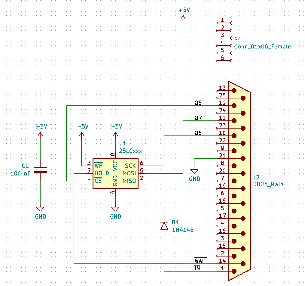
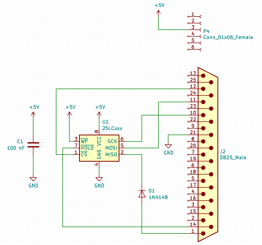
Serial EEPROM Connected to Centronics Connector (Switches and LEDs)
Sharing the LED and Switch port, you loose two LEDs and one switch. Possible conflict with the bootstrap loader, if there is a read sequence (CS and read pattern 0000 0011). To prevent this, set the EEPROM into HOLD state e.g. with the WAIT signal.| SPI | MC (Master) | 25LCxxxx (Slave) | Interface |
|---|---|---|---|
| MISO | J2.1 IN EF4 | 2 SO | diode e.g. 1N4148 |
| MOSI | J2.11 O7 LED7 | 5 SI | direct |
| CLK | J2.10 O6 LED6 | 6 SCK | direct |
| CS | J2.12 O5 LED5 | 1 CS | direct |
| P4.3 VDD | 8 VCC | +5V capacitor 100 nF to GND | |
| " | 3 WP | +5V | |
| J2.14 WAIT | 7 HOLD | direct | |
| 21 GND | 4 GND | GND |

- BCM 19 (SPI1 MISO) O5
- BCM 20 (SPI1 MOSI) -
- BCM 21 (SPI1 SCLK) shutdown
- BCM 18 (SPI1 CS0) CLR
- BCM 17 (SPI1 CS1) WAIT
- BCM 9 (SPI0 MISO) IN4
- BCM 10 (SPI0 MOSI) IN3
- BCM 11 (SPI0 SCLK) IN6
- BCM 8 (SPI0 CS0) IN7
- BCM 7 (SPI0 CS1) O0
Read Byte
CS0     EQU     0b1101111
CS1     EQU     0b0010000
CLK0    EQU     0b1011111
CLK1    EQU     0b0100000
DATA0   EQU     0b0111111
DATA1   EQU     0b1000000

        ; MSB first

READBYTE:
        LDI     0
        PLO     R5
        LDI     0xFF
        PHI     R6
        LDI     0xFF - 8
        PLO     R6
        SEX     R0
BITLOOP:
        OUT4,0b01000000      ; CLK for SPI
        OUT4,0b00000000
        INC     R6
        GHI     R6           ; set CARRY
        SHRC
        GLO     R5
        B4      SETBIT       ; branch if bit set
        SHL                  ; bit not set
        BR      SAVEBIT
SETBIT:
        SHLC
SAVEBIT:
        PLO     R5
        GLO     R6
        BNZ     BITLOOP
about 230 cycles for one byte -> 1 ms -> 1 KiB takes about 1 s @ 1.79 MHz
Write Byte
WRITEBYTE:
        LDI     0
        PHI     R6
        LDI     8
        PLO     R6
        SEX     R0
BITLOOP:
        GLO     R5           ; get the next bit
        SHLC                 , next bit is in the carry
        PLO     R5
        BDF     SETBIT
        OUT4,0b01000000      ; CLK for SPI with data bit cleared
        OUT4,0b00000000
        BR      NEXT
SETBIT:
        OUT4,0b11000000      ; CLK for SPI with data bit set
        OUT4,0b10000000
NEXT:
        DEC     R6
        GLO     R6
        BNZ     BITLOOP
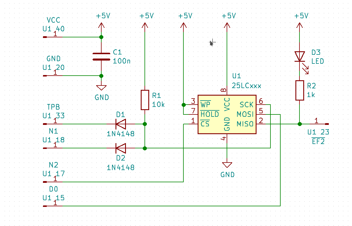
Serial EEPROM patched on MC PCB
SPI Mode 0, data is always latched in on the rising edge of SCK and always output on the falling edge of SCK. For CS one output port bis is needed e.g. O7 or N2 (INP4) to start/end operation (A high-to-low transition on the CS pin is required to start an operation and a low-to-high transition is required to end an operation).| SPI | MC (Master) | 25LCxxxx (Slave) | Interface |
|---|---|---|---|
| MISO | EF2 | 2 SO | direct |
| MOSI | D0 | 5 SI | direct |
| CLK | TPB & N1 (OUT2) | 6 SCK | wired AND |
| CS | N2 | 1 CS | direct |
| 8 VCC | +5V | ||
| 3 WP | +5V | ||
| J2.14 WAIT | 7 HOLD | direct | |
| 4 GND | GND |

Read Byte
        ; MSB first

        LDI     0
        PLO     R5
        LDI     0xFF
        PHI     R6
        LDI     0xFF - 8
        PLO     R6
        SEX     R6
BITLOOP:
        OUT2                 ; CLK for SPI, INC Rx
        GHI     R6           ; set CARRY
        SHRC
        GLO     R5
        B2      SETBIT       ; branch if bit set
        SHR                  ; bit not set
        BR      SAVEBIT
SETBIT:
        SHRC
SAVEBIT:
        PLO     R5
        GLO     R6
        BNZ     BITLOOP
about 200 cycles for one byte -> 1 ms -> 1 KiB takes about 1 s
Write Byte
WRITEBYTE:
        LDI     0
        PHI     R6
        LDI     8
        PLO     R6
        SEX     R0
BITLOOP:
        GLO     R5           ; get the next bit
        SHLC                 , next bit is in the carry
        PLO     R5
        LSNF
        OUT2,0b00000000      ; CLK for SPI with data bit cleared
        LSDF
        OUT2,0b00000001      ; CLK for SPI with data bit set
        DEC     R6
        GLO     R6
        BNZ     BITLOOP
Kermit/ZModem
What about using KERMIT or ZMODEM protocol for the file transfer and use the file system on the host? No need to add additional hardware (SD-card is anyway to modern You could use an old CP/M or even a PDP11 as host. The C-Kermit Local Server mode, e.g. MC can read/write the blocks as files
 block.0, block.2, block.255.
The serial communication is really slow, not only because of the 9600 baud, but you have to wait after each character to give CDP1802 some computation time.
https://github.com/utoh/pygmy-forth/blob/master/extras/kermit/pfkerm.docSpare Time Gizmos ELF2K ROM for RaspiElf
For details see Herb Johnson's ELF 2K ROM for 1802 Membership Cardpi@cosmac:~/elf/elf2k $ cp v88.hex v88.hex.org pi@cosmac:~/elf/elf2k $ patch v88.hex v88-mc.patch pi@cosmac:~/elf/elf2k $ hex2bin v88.hex hex2bin v2.5, Copyright (C) 2017 Jacques Pelletier & contributors Allocate_Memory_and_Rewind: Lowest address: 00000000 Highest address: 00007FFF Starting address: 00000000 Max Length: 32768 Binary file start = 00000000 Records start = 00000000 Highest address = 00007FFF Pad Byte = FF pi@cosmac:~/elf/elf2k $ bin2elf -s 8000 v88.bin 0x8000 bytes written pi@cosmac:~/elf/elf2k $ bin2elf -w -r LBR_8000.bin 0x0003 bytes written pi@cosmac:~/elf/elf2k $But there is "Post Code 88" -> SRAM size wrong My MC has 64 KiB RAM and no ROM. But the RAM Size Test (part of monitor) expects ROM from 0x8000. Herb Johnson wrote: Peter, hopefully you can take it from here, find the BOOTS.ASM code at the link below, and "patch" it to accept an appropriate area for RAM. More than I can figure out today. http://www.sparetimegizmos.com/Downloads/v88-source.zip
Comments


| I | Attachment | History | Action | Size | Date | Who | Comment |
|---|---|---|---|---|---|---|---|
| |
mc-eeprom-conn.png | r3 r2 r1 | manage | 20.4 K | 2019-01-19 - 23:12 | PeterSchmid | |
| |
mc-eeprom-u1.png | r2 r1 | manage | 18.6 K | 2019-01-23 - 21:26 | PeterSchmid | |
| |
v88-mc.patch | r1 | manage | 1.1 K | 2019-01-20 - 10:36 | PeterSchmid |
Topic revision: r19 - 2019-01-23 - PeterSchmid

 |
|
|
Ideas, requests, problems regarding TWiki? Send feedback