Difference: TrackWork (10 vs. 11)
Revision 112023-07-09 - PeterSchmid
| Line: 1 to 1 | |||||||||
|---|---|---|---|---|---|---|---|---|---|
%DASHBOARD{ section="banner" | |||||||||
| Line: 7 to 7 | |||||||||
| titlestyle="color:#F00000;" }% | |||||||||
| Deleted: | |||||||||
| < < | |||||||||
| Added: | |||||||||
| > > | Intro
Intro
Contents
| ||||||||
| Added: | |||||||||
| > > | |||||||||
| Changed: | |||||||||
| < < | Prototype | ||||||||
| > > | |||||||||
    | |||||||||
| Line: 37 to 45 | |||||||||
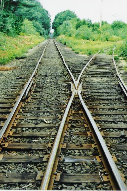
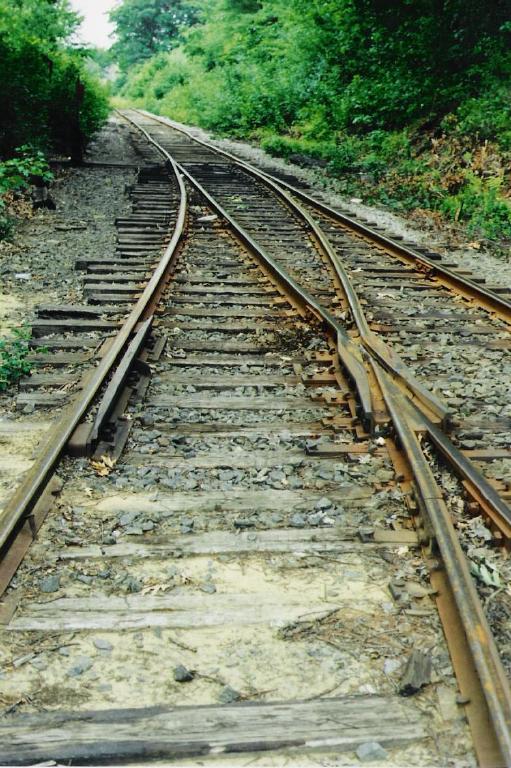
| Narrow gauge double slip switch. RhB Italy/Switzerland. | |||||||||
| Changed: | |||||||||
| < < | HOn30 Tracks | ||||||||
| > > | |||||||||
| Changed: | |||||||||
| < < | Rails | ||||||||
| > > | |||||||||
| One of the narrow gauge advantages was the use of lighter rails and therefore the lower investment. Lighter rail looks better and is more prototypical. The rails were 33' long til about 1925. | |||||||||
| Line: 72 to 84 | |||||||||
| A good compromise is to use code 55 rail for HOn30 and code 70 for standard gauge. Ties | |||||||||
| Changed: | |||||||||
| < < | Ties | ||||||||
| > > | Ties | ||||||||
| |||||||||
| Line: 120 to 132 | |||||||||
| FR-4 is a composite of a resin epoxy reinforced with a woven fiberglass mat (epoxy resin bonded glass fabric (ERBGF), Veroboard) printed circuit board (PCB) | |||||||||
| Changed: | |||||||||
| < < | Spikes | ||||||||
| > > | Spikes | ||||||||
Cut spikes are about 6" long, the spike head is about 1 9/16" x 1 5/16" in HO is this 1.75 x 0.46 x 0.38 mm. The small spikes from Micro Engineering are 8.0 x 1.7 x 1.0 mm, they are far too large. You can build your own spike from 0.4 mm wire, you have to drill holes into the ties too. That's why I omit the spikes.
 | |||||||||
| Changed: | |||||||||
| < < | Tie Plates | ||||||||
| > > | Tie Plates | ||||||||
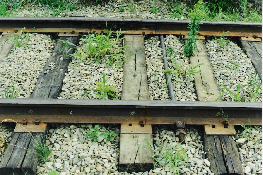
| Tie plates were not always used for narrow gauge tracks. But normally they were found at least on turnouts and in curves. They are 5" to 10" wide and about 1/2" (HO 0.15 mm) thick. Tie plates for HO are too small and too difficult to build for me. I omit tie plates on my tracks. | |||||||||
| Changed: | |||||||||
| < < | Tips | ||||||||
| > > | |||||||||
| Changed: | |||||||||
| < < | Tools needed | ||||||||
| > > | |||||||||
| |||||||||
| Line: 142 to 158 | |||||||||
| |||||||||
| Changed: | |||||||||
| < < | Soldering tips | ||||||||
| > > | Soldering tips | ||||||||
| |||||||||
| Line: 152 to 168 | |||||||||
| |||||||||
| Changed: | |||||||||
| < < | How To Scratch Build a Narrow Gauge Standard Gauge Crossing | ||||||||
| > > | |||||||||
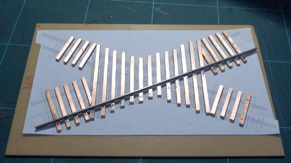
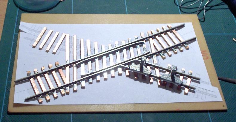
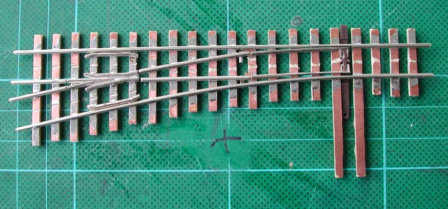
| As far as I know there is no commercial narrow gauge standard gauge crossing available. It takes me about 4 h to build a "diamond" from scratch. You need only only some code 70 rails and PCB cross ties. Step by step instructions to build a crossing from scratch: | |||||||||
| Changed: | |||||||||
| < < | Print out a template | ||||||||
| > > | Print out a template | ||||||||
e.g. from Fast Tracks " target="_blank">http://www.handlaidtrack.com/]]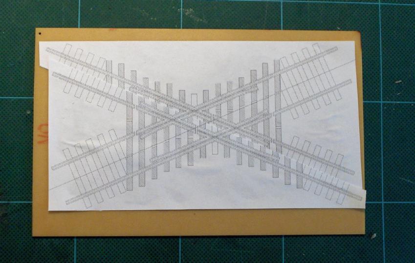 | |||||||||
| Changed: | |||||||||
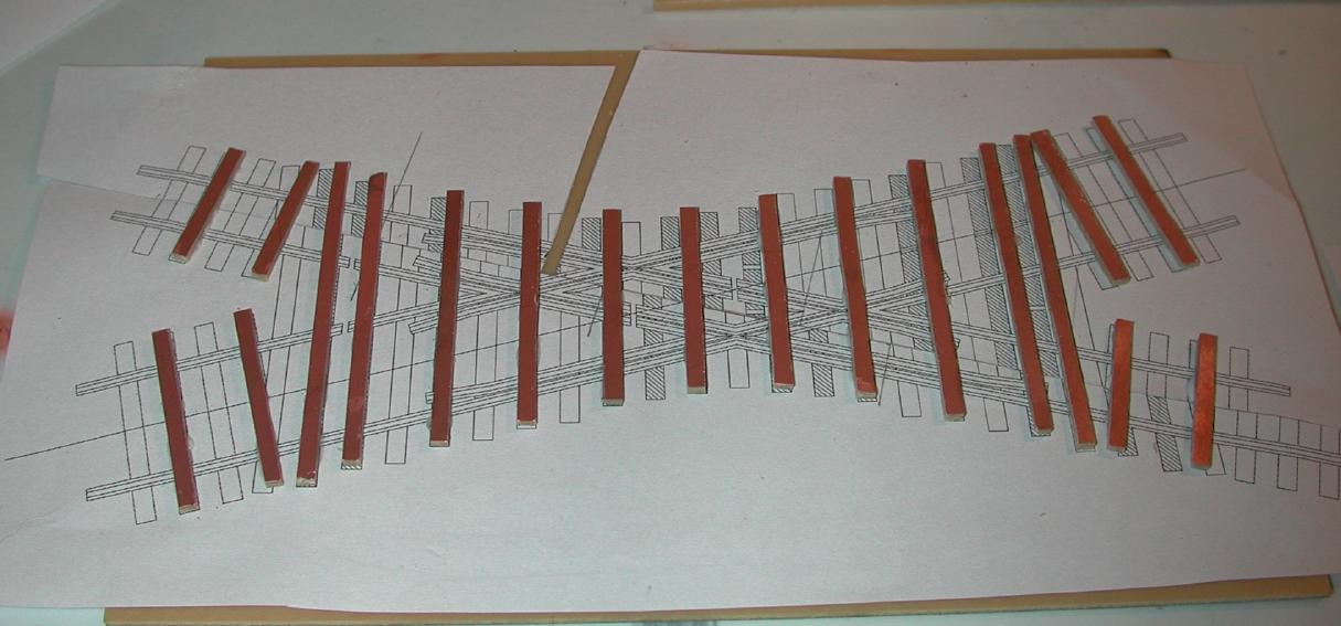
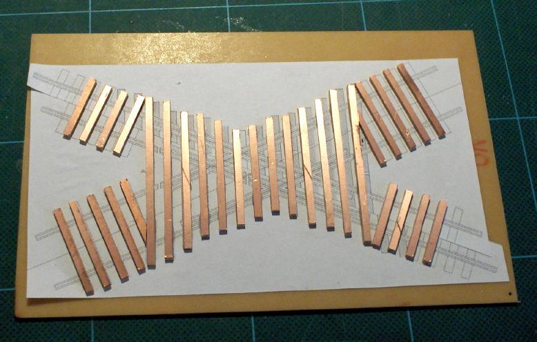
| < < | Glue the crossties to the template | ||||||||
| > > | Glue the crossties to the template | ||||||||
For the first crossing I built, I used for every second tie a PCB tie. Now I use for all ties PCB ties.
  | |||||||||
| Changed: | |||||||||
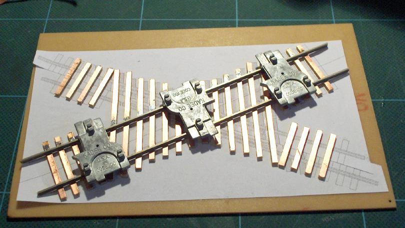
| < < | Solder the first rail from the mainline (usually the standard gauge leg) to the ties | ||||||||
| > > | Solder the first rail from the mainline (usually the standard gauge leg) to the ties | ||||||||
Solder the second rail to the ties, use a HO track gauge to ensure the right distance between the rails.
  | |||||||||
| Changed: | |||||||||
| < < | Bend the two guard rails for the mainline and solder the rails next to the mainline rails | ||||||||
| > > | Bend the two guard rails for the mainline and solder the rails next to the mainline rails | ||||||||
Check the flangeways with a NMRA HO gauge.
 | |||||||||
| Changed: | |||||||||
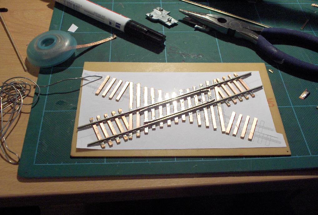
| < < | Bevel the end of a rail and solder the first crossing rail to the ties and to mainline rail | ||||||||
| > > | Bevel the end of a rail and solder the first crossing rail to the ties and to mainline rail | ||||||||
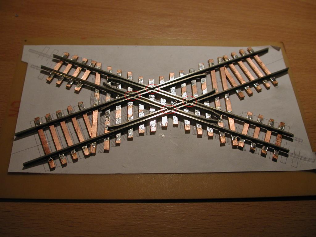
The rail heads should touch each other, to achive this I remove about 1 mm from the base of the crossing rail. Solder second crossing rail to the ties and to mainline rail, use N track gauge to ensure the right distance between the rails.
  | |||||||||
| Changed: | |||||||||
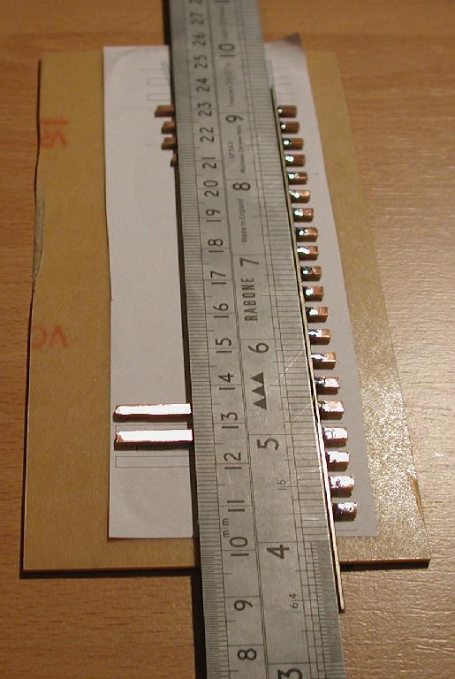
| < < | Cut and bevel a rail to the length between the two mainline guardrails | ||||||||
| > > | Cut and bevel a rail to the length between the two mainline guardrails | ||||||||
| Use a straight edge to guide the rail and solder the rail to the ties. Finish the crossing rails | |||||||||
| Changed: | |||||||||
| < < | Bend the outer guard rails for the narrow gauge line with a needle nose pliers | ||||||||
| > > | Bend the outer guard rails for the narrow gauge line with a needle nose pliers | ||||||||
| Bevel the ends and solder the rails to the PCB ties. Insert the inner guard rails for the narrow gauge line. | |||||||||
| Changed: | |||||||||
| < < | Cut the mainline rails and the guard rails for the HOn30 flangeways with a cutting disc moto tool. | ||||||||
| > > | Cut the mainline rails and the guard rails for the HOn30 flangeways with a cutting disc moto tool. | ||||||||
 | |||||||||
| Changed: | |||||||||
| < < | Put the crossing in warm soapy water and remove the crossing from the PCB | ||||||||
| > > | Put the crossing in warm soapy water and remove the crossing from the PCB | ||||||||
Cut the isolating gaps with the fretsaw trough the rails and the ties.
 | |||||||||
| Changed: | |||||||||
| < < | How To Convert an Atlas N Code 55 Turnout to HOn30 | ||||||||
| > > | |||||||||
|
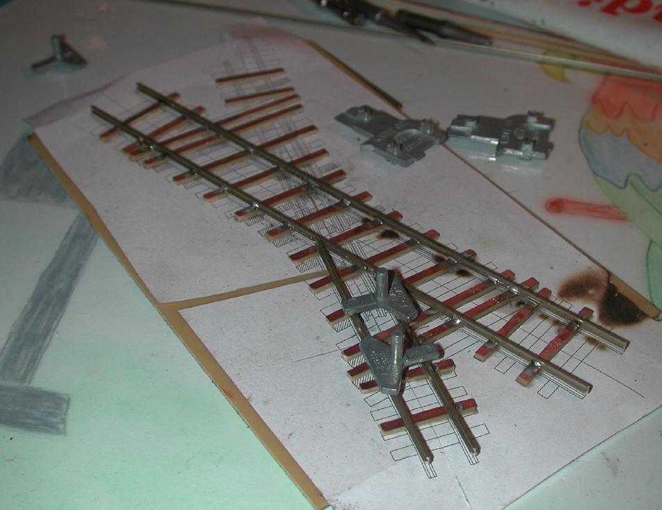
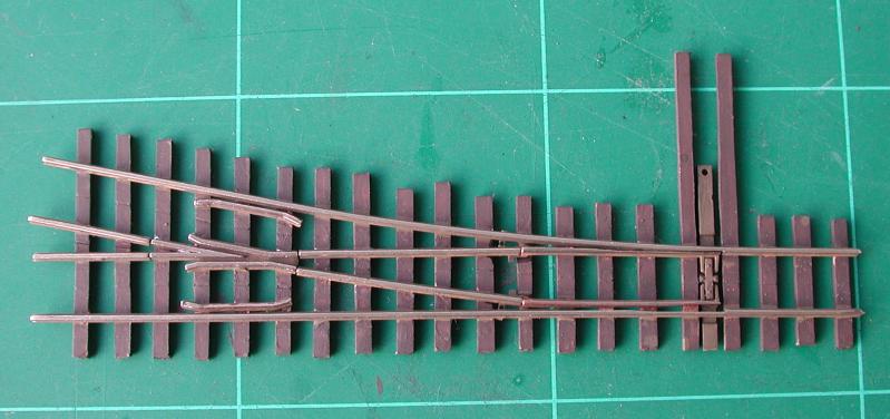
Commercial available HOn30/H0e/009 turnouts from Peco, Tillig, Technomodell, and Roco have too heavy rails (Code 80/83) and too wide angles (15 °, less than #4). You can build the turnouts from scratch, but for me it is difficult and to time-consuming to build the heel of the switch (especially the hinge) and the frog. The N code 55 turnouts from Atlas are available with frog numbers #5 and #7 (for details see http://www.atlasrr.com/Trackmisc/ncode55.htm | |||||||||
| Changed: | |||||||||
| < < | Print out a template | ||||||||
| > > | Print out a template | ||||||||
|
e.g. from Fast Tracks " target="_blank">http://www.handlaidtrack.com/]] | |||||||||
| Changed: | |||||||||
| < < | Remove the rails from the plastic ties | ||||||||
| > > | Remove the rails from the plastic ties | ||||||||
| Remove the pins from the frog and the guard rails. | |||||||||
| Changed: | |||||||||
| < < | Glue the crossties to the template | ||||||||
| > > | Glue the crossties to the template | ||||||||
| Changed: | |||||||||
| < < | Solder the straight stock rail to the ties | ||||||||
| > > | Solder the straight stock rail to the ties | ||||||||
Use a straight edge as a guide.
 | |||||||||
| Changed: | |||||||||
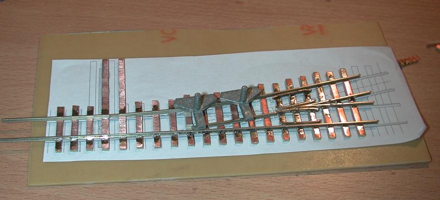
| < < | Solder the frog to the ties | ||||||||
| > > | Solder the frog to the ties | ||||||||
| Use a NMRA N gauge to check the distance between the stock rail an the frog. The lead (distance between toe of point and frog point) is 75 mm. | |||||||||
| Changed: | |||||||||
| < < | Solder the second stock rail to the ties | ||||||||
| > > | Solder the second stock rail to the ties | ||||||||
| Check the gauge between the stock rails and between the stock rail and the frog. | |||||||||
| Changed: | |||||||||
| < < | Solder the two rails to the frog heel (frog point rail) and to the frog toe (closure rails) | ||||||||
| > > | Solder the two rails to the frog heel (frog point rail) and to the frog toe (closure rails) | ||||||||
Use a N track gauges to ensure the right distance between the rails. Solder the two guard rails to the rails.
 | |||||||||
| Changed: | |||||||||
| < < | Solder the switch tabs to the heel of the point | ||||||||
| > > | Solder the switch tabs to the heel of the point | ||||||||
| Make sure that the rails are in line. | |||||||||
| Changed: | |||||||||
| < < | Cut gaps into the copper foil ties | ||||||||
| > > | Cut gaps into the copper foil ties | ||||||||
 | |||||||||
| Changed: | |||||||||
| < < | Put the turnout in warm soapy water and remove the turnout from the PCB. | ||||||||
| > > | Put the turnout in warm soapy water and remove the turnout from the PCB. | ||||||||
Fill the gaps with filler, sand and paint the turnout.
 | |||||||||
| Changed: | |||||||||
| < < | HOn30 #5 Turnout in Comparison With Shinohara HO #6 Code 100 | ||||||||
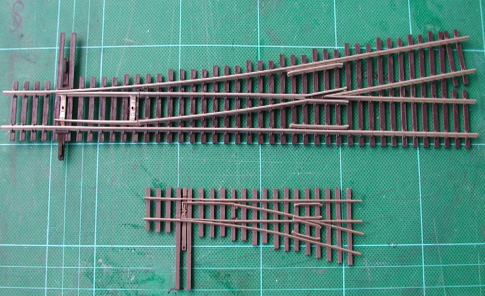
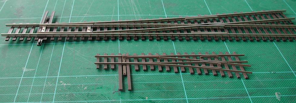
| > > | HOn30 #5 Turnout in Comparison With Shinohara HO #6 Code 100 | ||||||||
  | |||||||||
| Changed: | |||||||||
| < < | Bibliography | ||||||||
| > > | |||||||||
| |||||||||
| Line: 270 to 299 | |||||||||
| Added: | |||||||||
| > > | |||||||||
| Added: | |||||||||
| > > | |||||||||
-- PeterSchmid - 2011-05-09
 | |||||||||
| Line: 349 to 381 | |||||||||
| |||||||||
| Added: | |||||||||
| > > |
| ||||||||
View topic | History: r14 < r13 < r12 < r11 | More topic actions...
Ideas, requests, problems regarding TWiki? Send feedback