HOn30 Trackwork Mini HowTo
Intro
 |
 |
 |
|
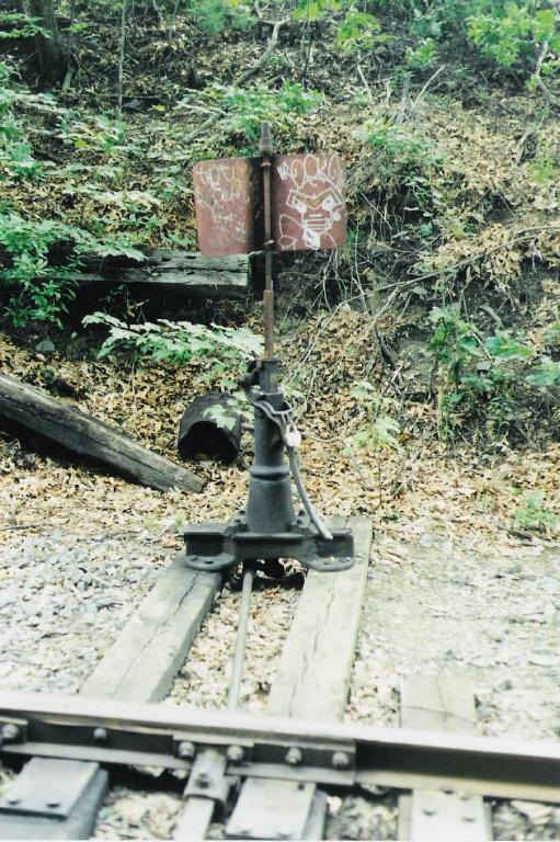
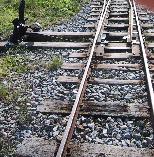
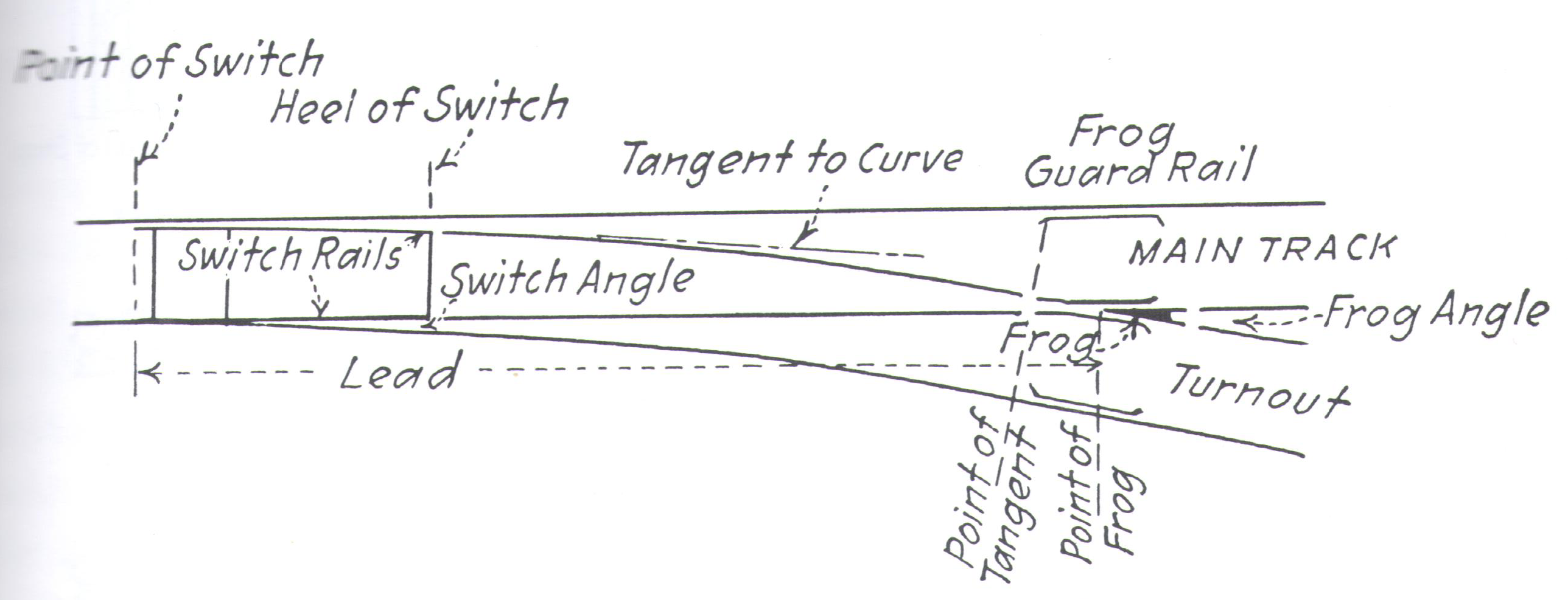
Prototype
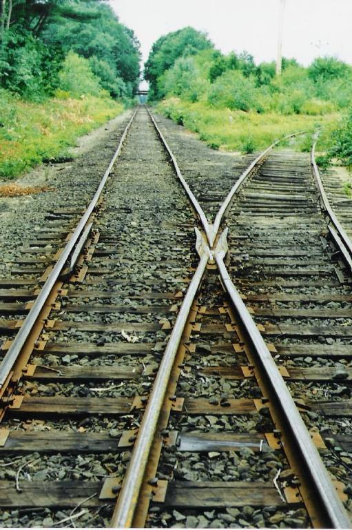
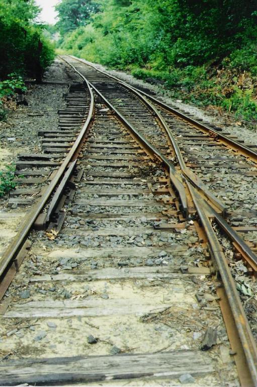
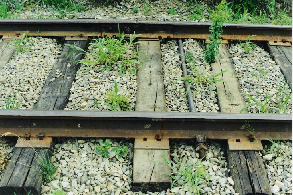
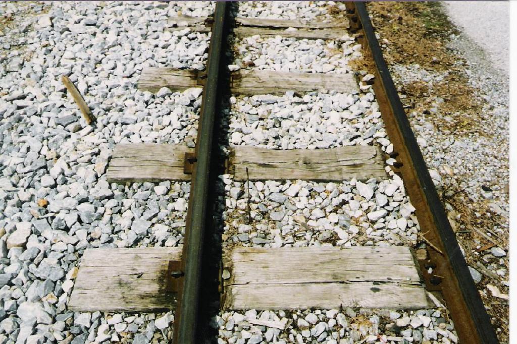
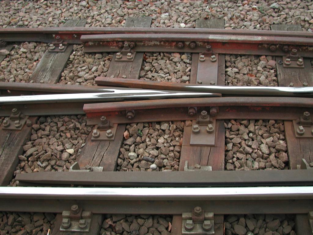
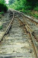
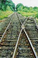
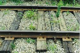
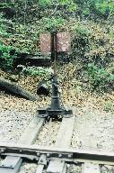
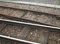
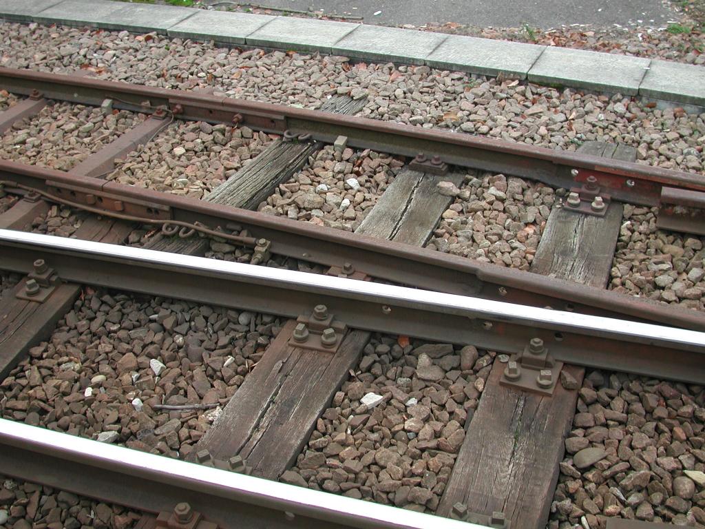
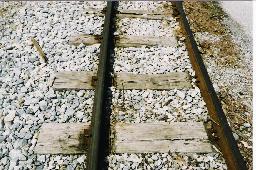
 Standard gauge trackwork somewhere in New England. Wood ties and nails are still used in 1996. You can see a rail anchor in the third picture, a detail very seldom modelled.
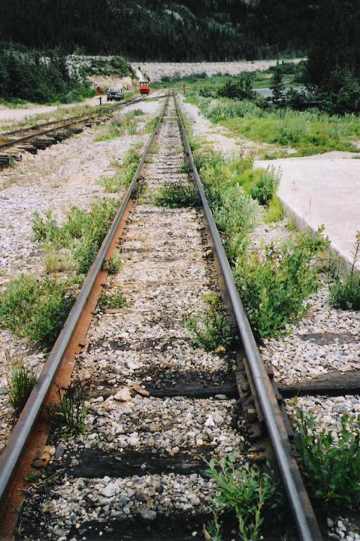
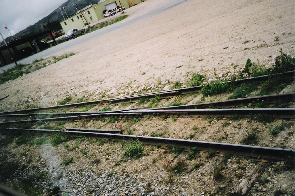
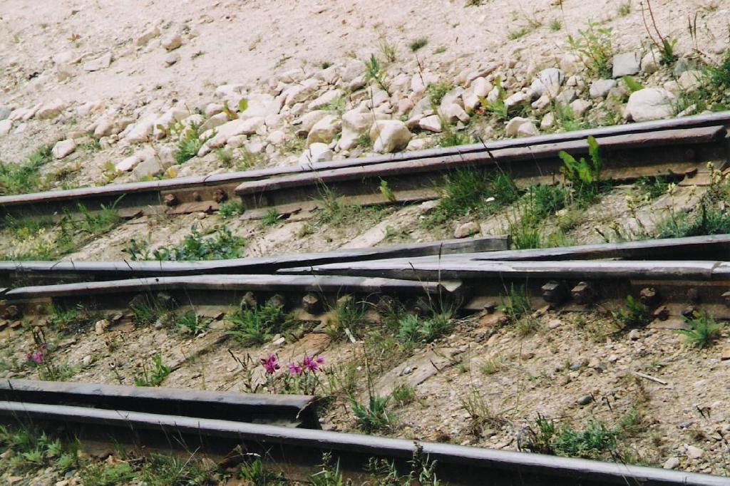 A friend gave me some photos from the 3 foot narrow gauge railroad White Pass and Yukon Route. Maybe original tracks from 1898.
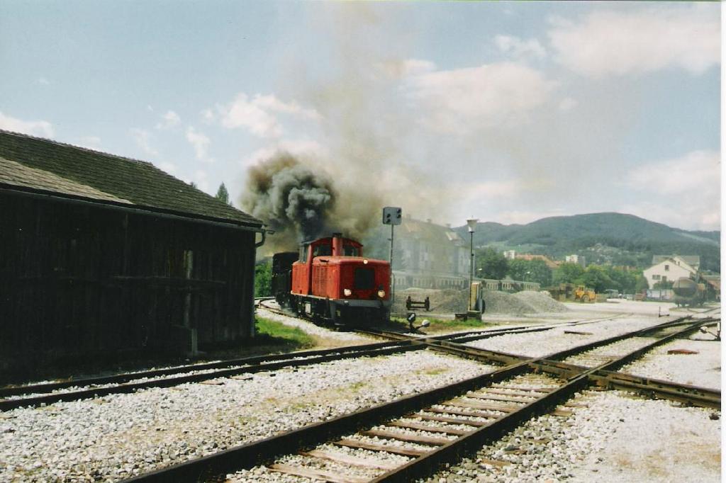
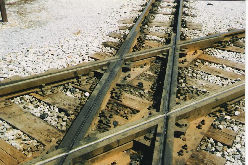
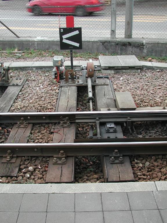
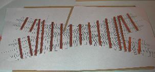
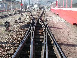
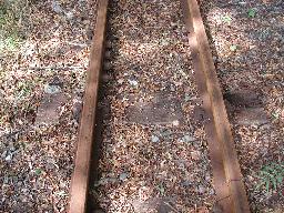
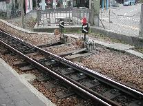
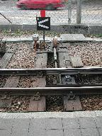
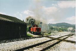
 You can see a 76 cm narrow gauge line crossing two standard gauge tracks in Weiz, Austria. The Switch is in Bikfeld. The trackwork looks very american for my opinion.
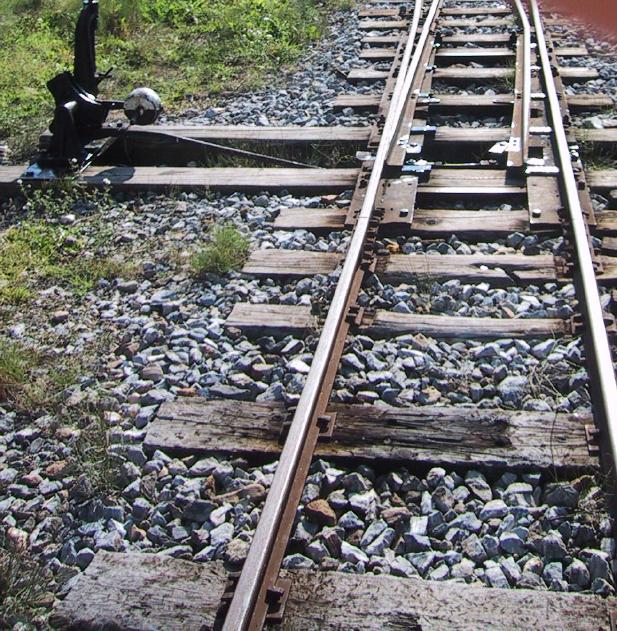
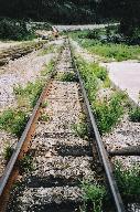
 Some industrial 60 cm and 75 cm gauge trackwork in Switzerland.

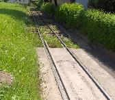
 Waldenburger Bahn, the only 75 cm gauge commuter train in Switzerland (probably in the world).
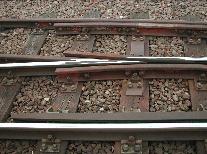
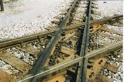
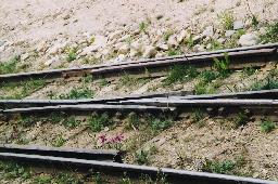
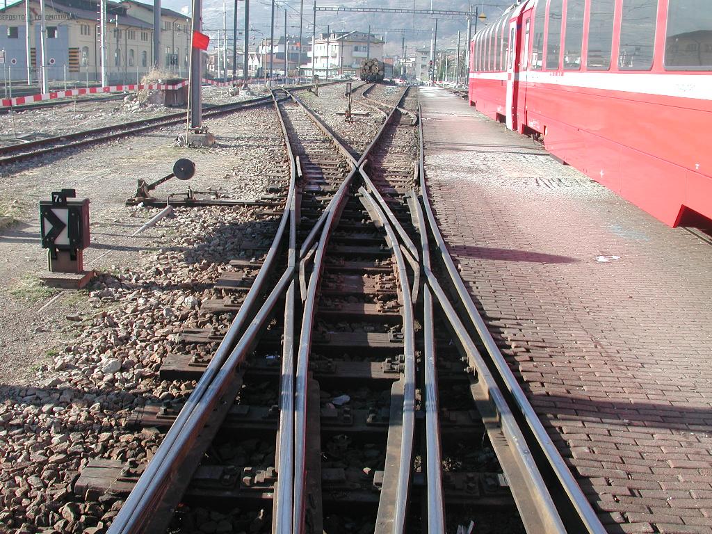 Narrow gauge double slip switch. RhB Italy/Switzerland.
HO / HOn30 Tracks
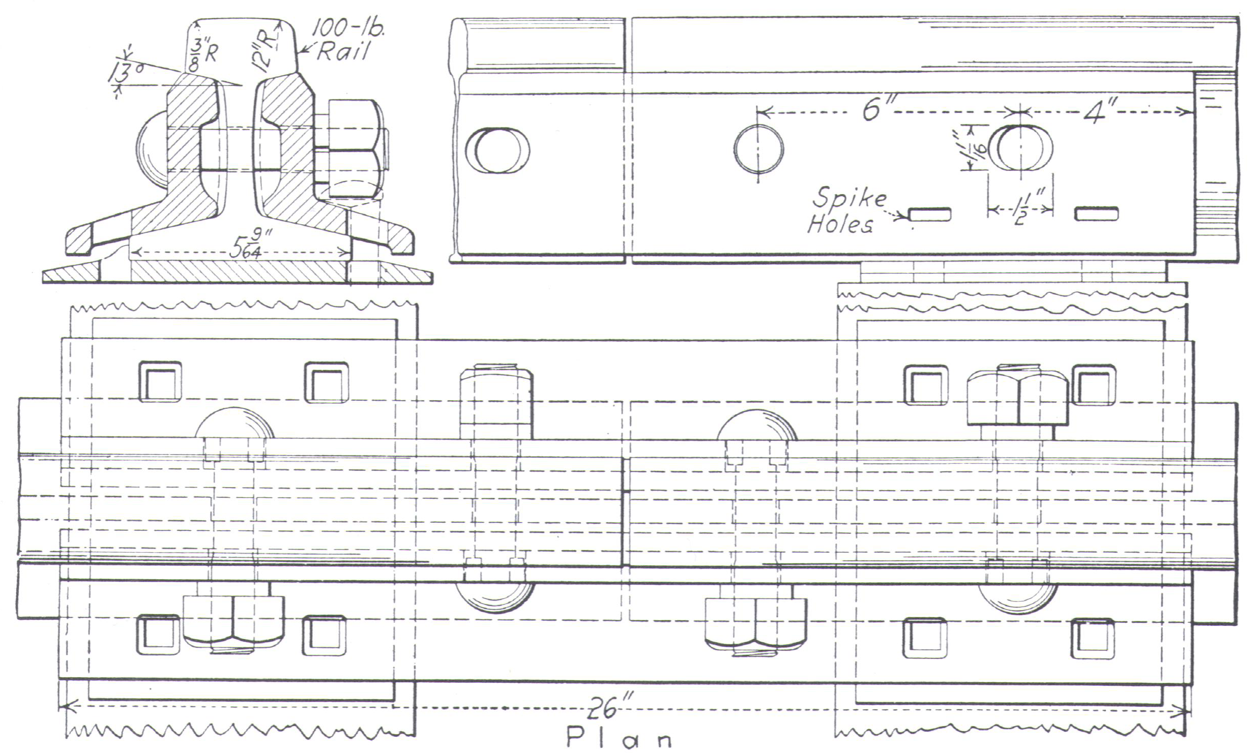
Rails
One of the narrow gauge advantages was the use of lighter rails and therefore the lower investment. Lighter rail looks better and is more prototypical. The rails were 33' long til about 1925.| Rail Code | Height [mm] | Weight [Pounds per Yard] | Weight [kg/m] | DIN 5901 |
|---|---|---|---|---|
| 40 | 1.0 | 40 | 18.3 | S 18 |
| 55 | 1.4 | 80 | 33.5 | S 33 |
| 70 | 1.8 | 100 | 54.5 | S 54 |
| 80 | 2.0 | 136 | 64.9 | S 64 |
| 83 | 2.1 | 140 | 64.9 | S 64 |
| 100 | 2.5 | 156 | - | - |
 Quotation from Maine Two Footers On2 FAQ:
- SR&RL rail weights, information from 1916, but weights probably did not change too much after then (before that is not a simple answer)
- Farmington - Strong - Phillips weights varied from 50 - 52 - 56 & 58 1/4 lbs (most of it 10.48 mi. was 52lb).
- Phillips to Madrid Jct. 50 lb rail laid in 1919
- Almost everything else was 35 lb rail
- At time of abandonment, there was a reported 2 mi. of 60 lb rail
- B&B Rail was 25 lb, 30ft lengths.
- B&SR Rail Weights
- Bridgton Jct to Bridgton, prior to 1909: 30 & 35 lbs
- Bridgton Jct to Bridgton, after 1909 : 50 lbs.
- Bridgton yard relaid with 50 lbs rail in 1910
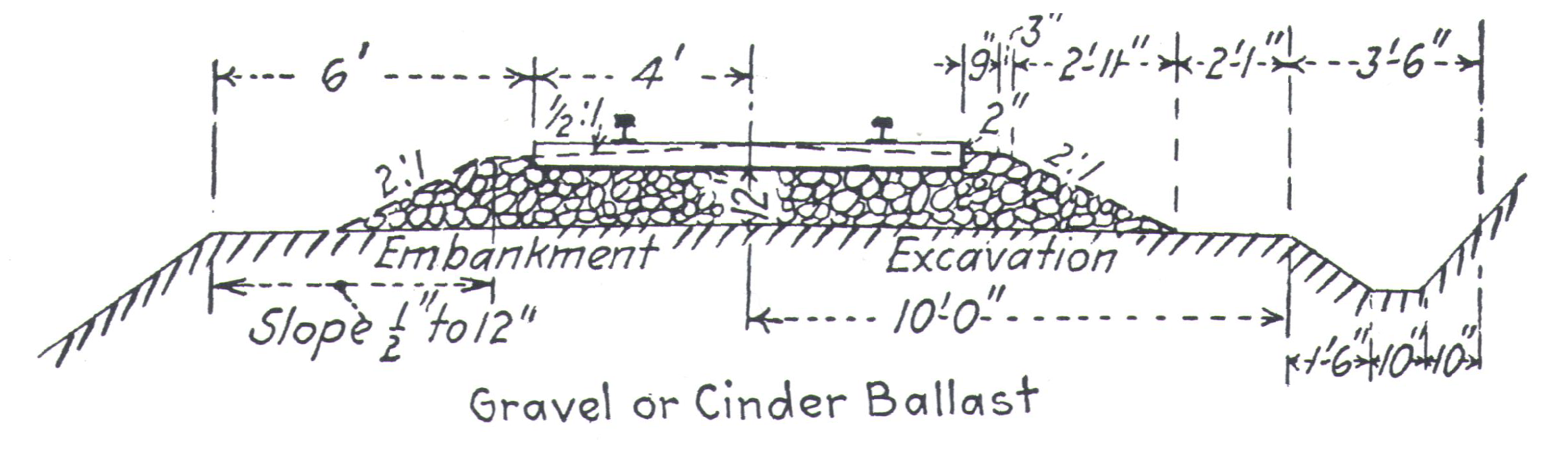
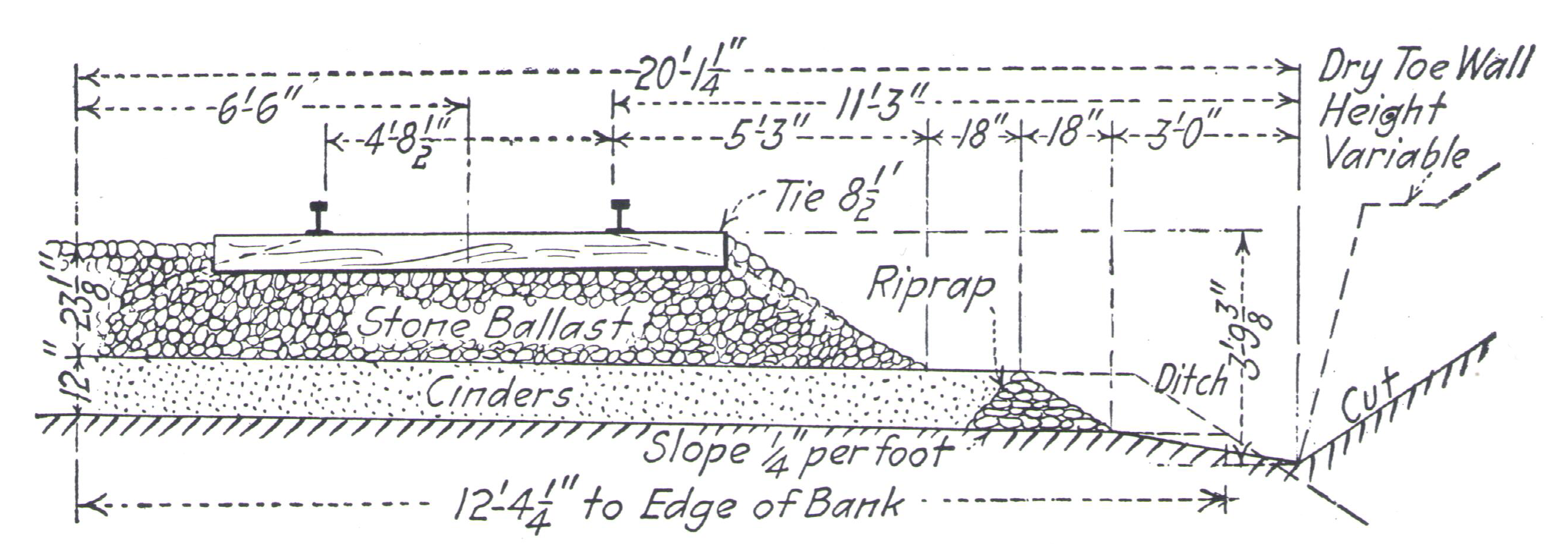
Ties
- Standard gauge until 1918: 8' long (HO 28 mm)
- Standard gauge after 1918: 8.5' long (HO 29.8 mm), sometimes 9' (HO 31.5 mm)
- width: 7 .. 9" (HO 2 .. 2.6 mm), thickness: 7 .. 8" (HO 2 .. 2.3 mm)
| center-to-center main lines | 22" | 6.4 mm |
| center-to-center sidings | 24.8" | 7.2 mm |
| center-to-center yards | 28.3" | 8.3 mm |
| Width | 200 mm | 2.3 mm |
| Length | 1.7 m | 20 mm |
| center-to-center main lines | 750 mm | 8.6 mm |
| center-to-center sidings | 830 mm | 9.5 mm |
| Width | 5" | 1.5 mm |
| Length | 5' | 17.5 mm |
| HO | 1.3 x 2.4 x 28 mm |
| H0n3 | 1.3 x 2.4 x 21 mm |
| HOn3 | 1.7 x 2.3 x 23.5 mm |
| HOn3 | 1.6 x 2.0 x 24.4 mm |
| HOn30 | 1.6 x 2.0 x 20.1 mm |
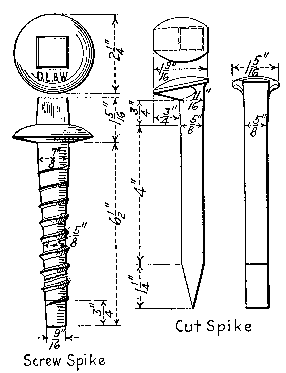
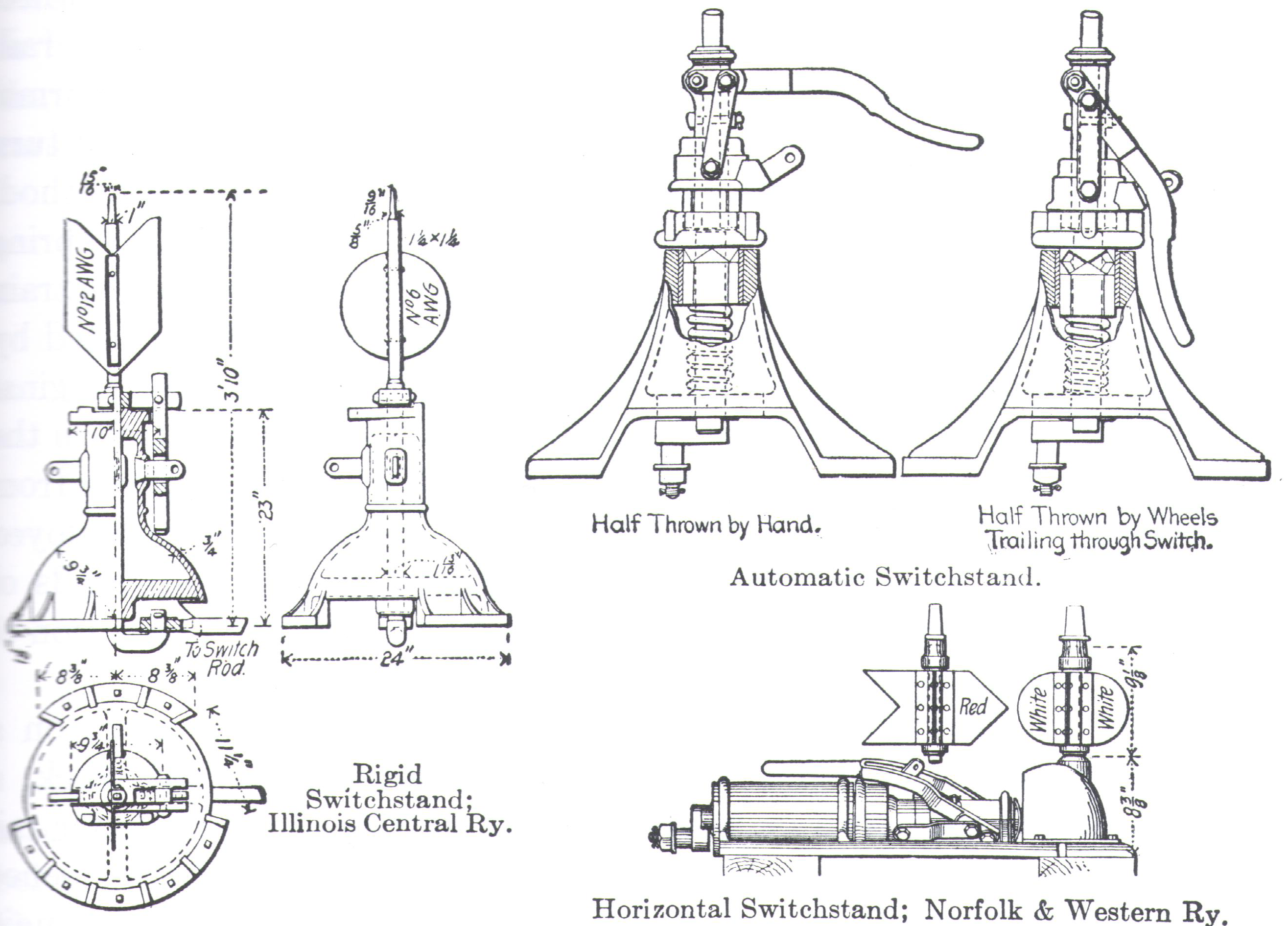
Spikes
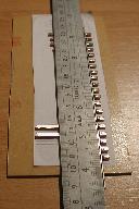
Cut spikes are about 6" long, the spike head is about 1 9/16" x 1 5/16" in HO is this 1.75 x 0.46 x 0.38 mm. The small spikes from Micro Engineering are 8.0 x 1.7 x 1.0 mm, they are far too large. You can build your own spike from 0.4 mm wire, you have to drill holes into the ties too. That's why I omit the spikes.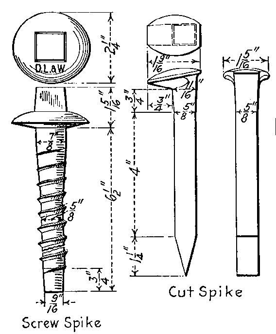
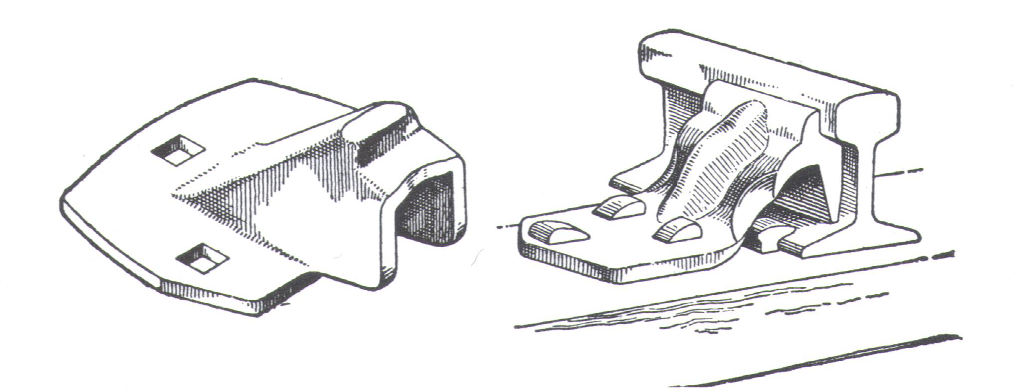
Tie Plates
Tie plates were not always used for narrow gauge tracks. But normally they were found at least on turnouts and in curves. They are 5" to 10" wide and about 1/2" (HO 0.15 mm) thick. Tie plates for HO are too small and too difficult to build for me. I omit tie plates on my tracks.Tips
Tools needed
- Moto tool with a cutting disc or alternative needle files (Swiss files) and lot of patience
- Jewelers Saw
- Regulated Soldering iron e.g. from Weller
- Fretsaw
- Wire cutting pliers
- Needle nose pliers
- NMRA Standards gage for HO and N
- track gauges for HO and N e.g. from Rail Craft
Soldering tips
- use a regulated soldering iron e.g. from Weller
- use small diameter electronic grade solder
- flux is already included in the electronic grade solder (additional flux is not needed)
- solder only from the outside of the rail
- clean all surfaces: the rail, the PCB, and the tip of the soldering iron (dirt is the enemy of a good quality soldered joint)
- heat both the PCB and the rail before adding the solder
- remove excess solder with desoldering braid (Soder-Wick)
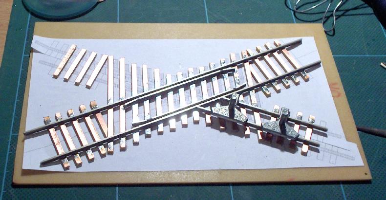
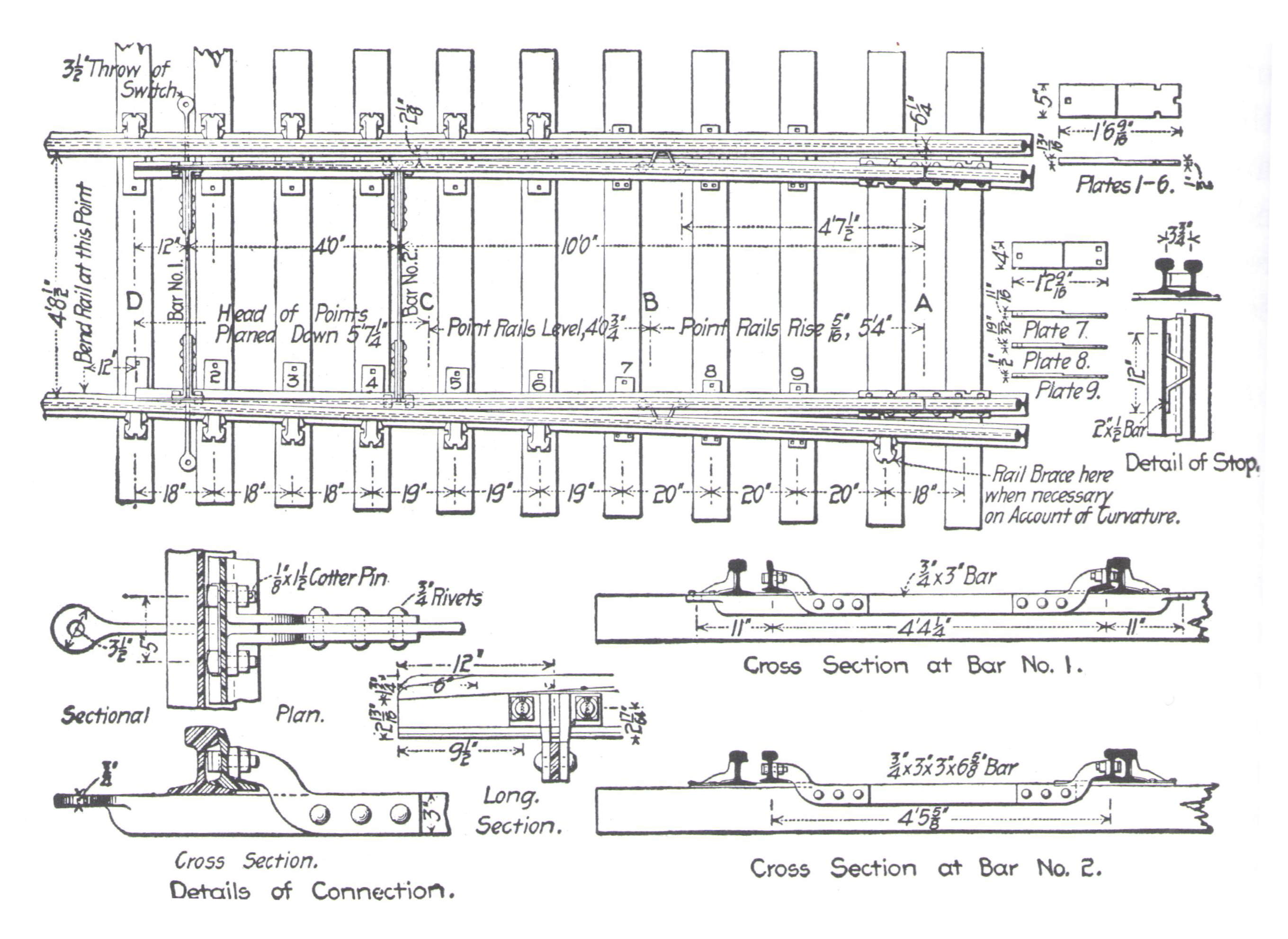
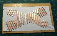
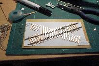
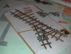
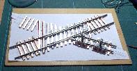
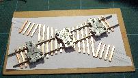
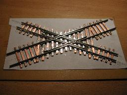
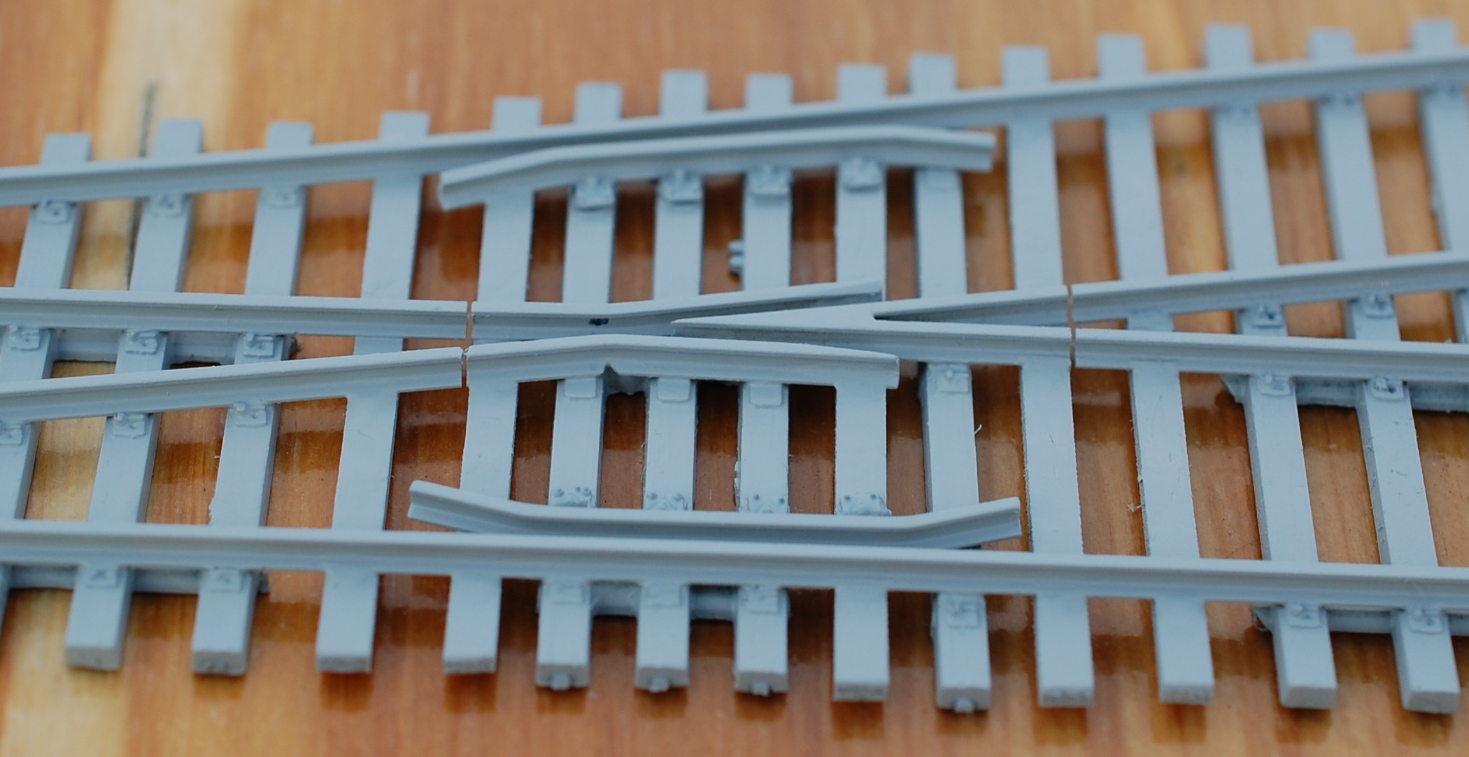
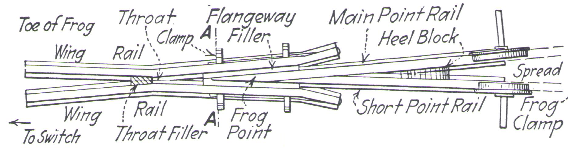
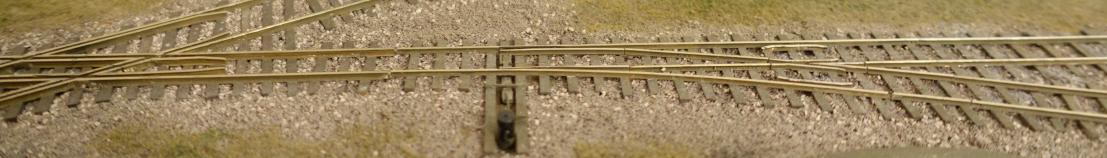
How To Scratch Build a Narrow Gauge Standard Gauge Crossing
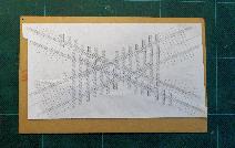
As far as I know there is no commercial narrow gauge standard gauge crossing available. It takes me about 4 h to build a "diamond" from scratch. You need only only some code 70 rails and PCB cross ties. Step by step instructions to build a crossing from scratch:Print out a template
e.g. from Fast Tracks " target="_blank">http://www.handlaidtrack.com/]]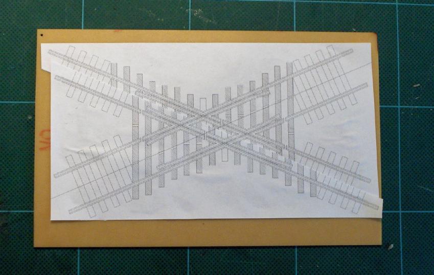
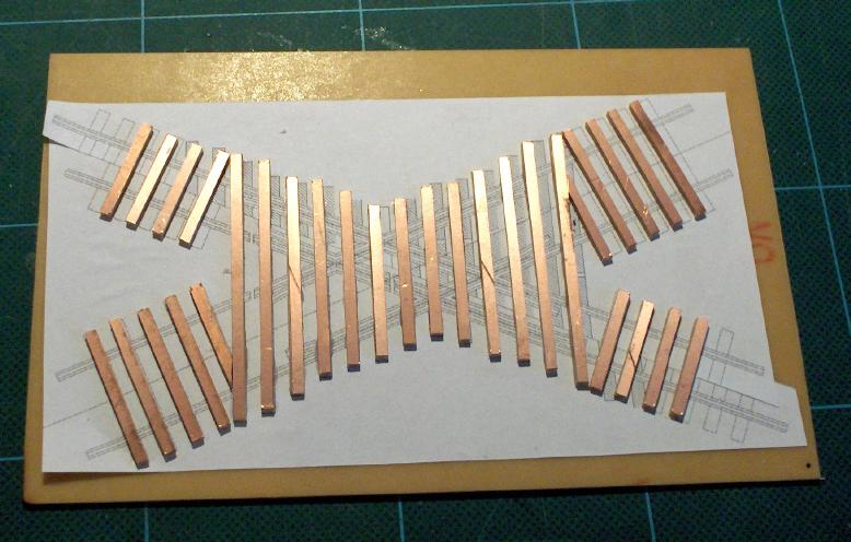
Glue the crossties to the template
For the first crossing I built, I used for every second tie a PCB tie. Now I use for all ties PCB ties.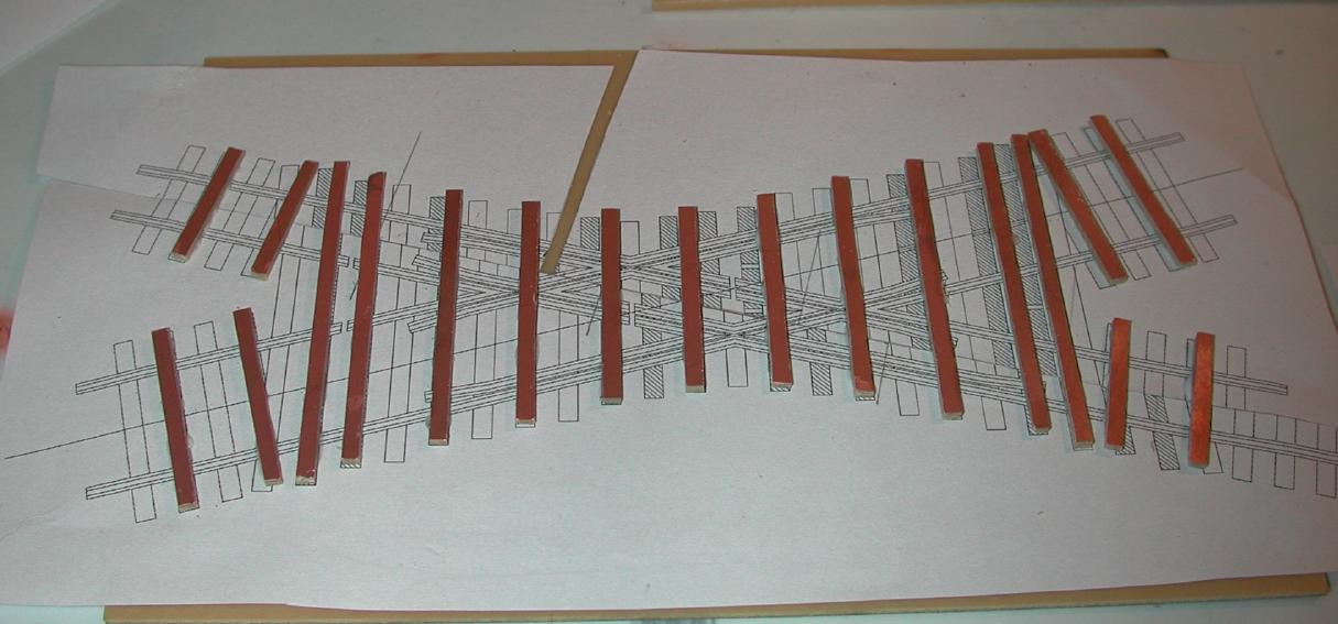
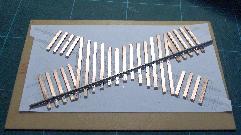
Solder the first rail from the mainline (usually the standard gauge leg) to the ties
Solder the second rail to the ties, use a HO track gauge to ensure the right distance between the rails.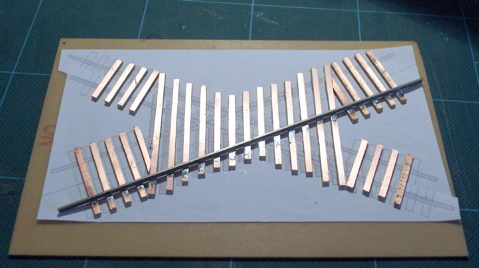
Bend the two guard rails for the mainline and solder the rails next to the mainline rails
Check the flangeways with a NMRA HO gauge.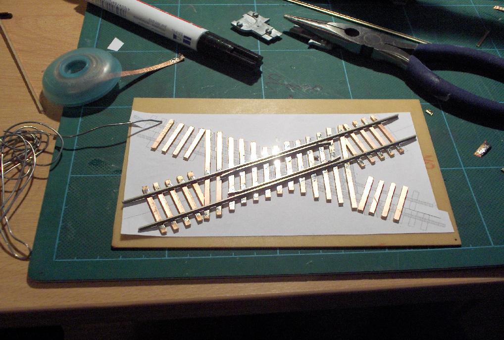
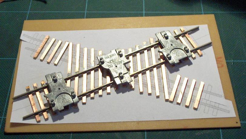
Bevel the end of a rail and solder the first crossing rail to the ties and to mainline rail
The rail heads should touch each other, to achive this I remove about 1 mm from the base of the crossing rail. Solder second crossing rail to the ties and to mainline rail, use N track gauge to ensure the right distance between the rails.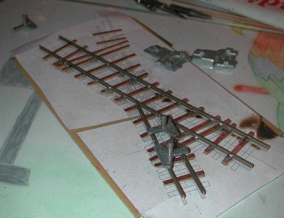
Cut and bevel a rail to the length between the two mainline guardrails
Use a straight edge to guide the rail and solder the rail to the ties. Finish the crossing railsBend the outer guard rails for the narrow gauge line with a needle nose pliers
Bevel the ends and solder the rails to the PCB ties. Insert the inner guard rails for the narrow gauge line.Cut the mainline rails and the guard rails for the HOn30 flangeways with a cutting disc moto tool.
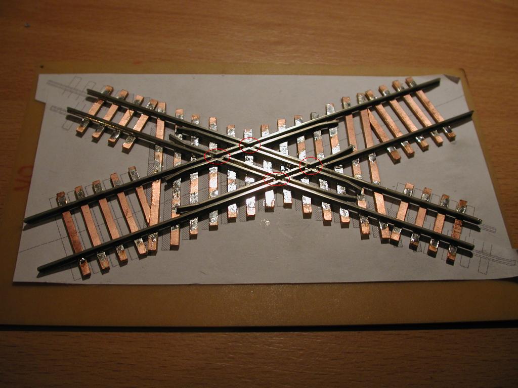
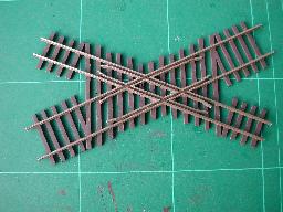
Put the crossing in warm soapy water and remove the crossing from the PCB
Cut the isolating gaps with the fretsaw trough the rails and the ties.
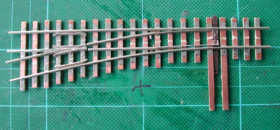
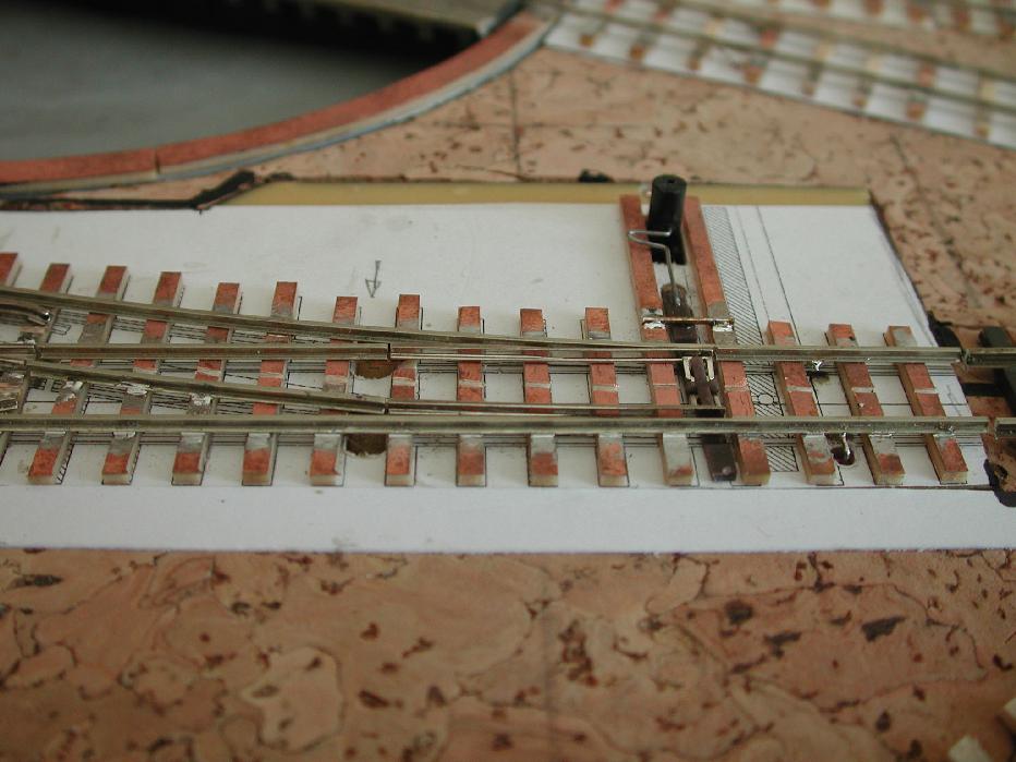
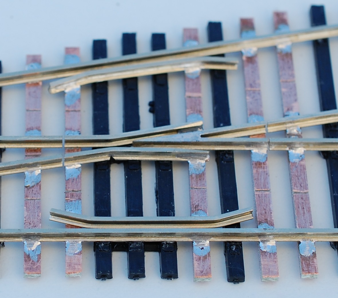
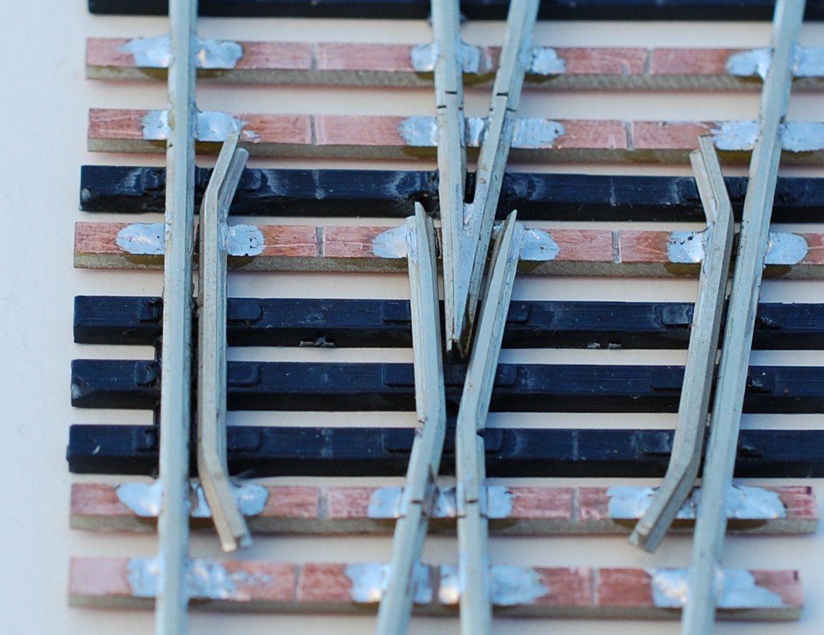
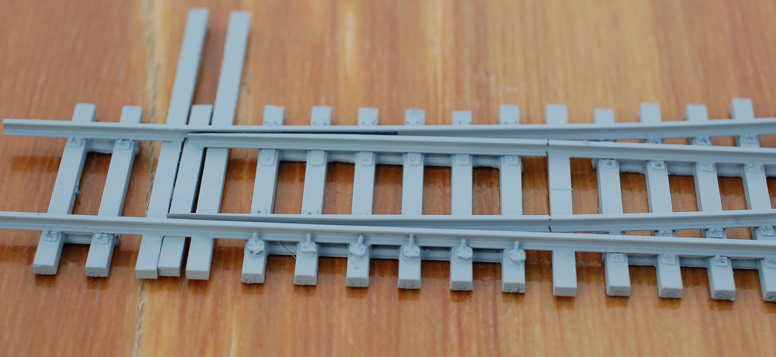
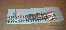
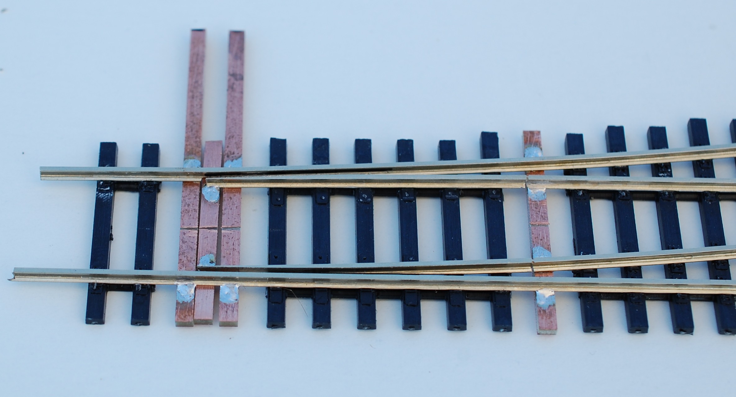
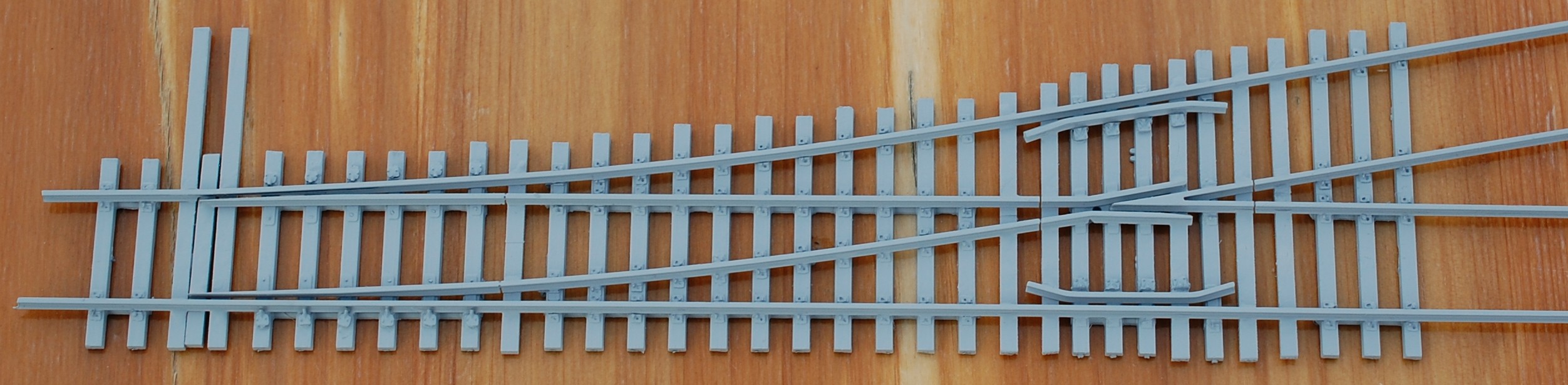
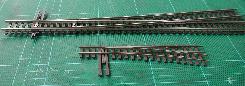
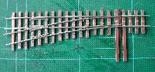
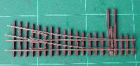
How To Convert an Atlas N Code 55 Turnout to HOn30
Commercial available HOn30/H0e/009 turnouts from Peco, Tillig, Technomodell, and Roco have too heavy rails (Code 80/83) and too wide angles (15 °, less than #4). You can build the turnouts from scratch, but for me it is difficult and to time-consuming to build the heel of the switch (especially the hinge) and the frog. The N code 55 turnouts from Atlas are available with frog numbers #5 and #7 (for details see http://www.atlasrr.com/Trackmisc/ncode55.htmPrint out a template
e.g. from Fast Tracks " target="_blank">http://www.handlaidtrack.com/]]Remove the rails from the plastic ties
Remove the pins from the frog and the guard rails.Glue the crossties to the template
Solder the straight stock rail to the ties
Use a straight edge as a guide.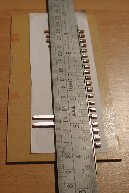
Solder the frog to the ties
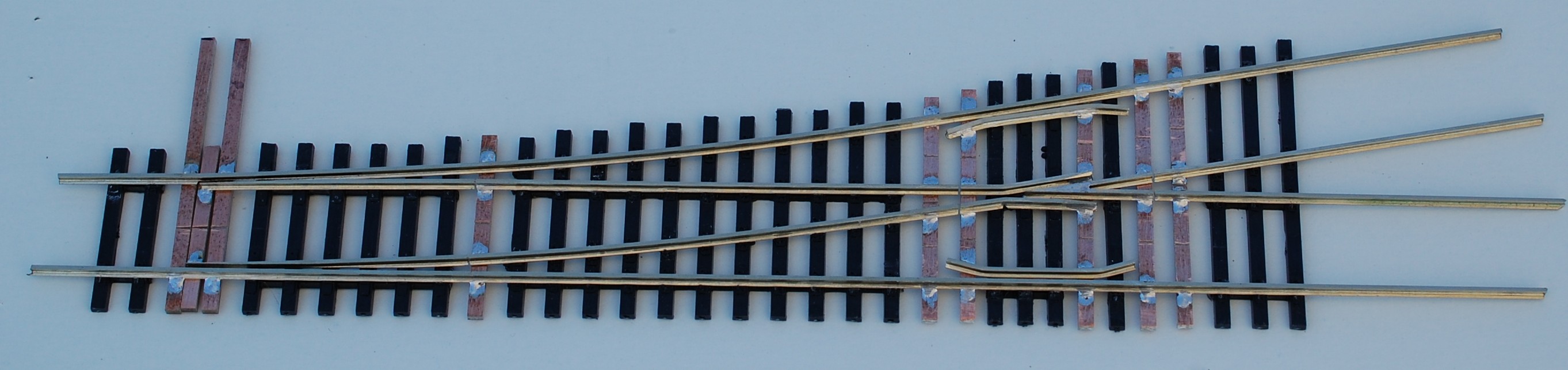
Use a NMRA N gauge to check the distance between the stock rail an the frog. The lead (distance between toe of point and frog point) is 75 mm.Solder the second stock rail to the ties
Check the gauge between the stock rails and between the stock rail and the frog.Solder the two rails to the frog heel (frog point rail) and to the frog toe (closure rails)
Use a N track gauges to ensure the right distance between the rails. Solder the two guard rails to the rails.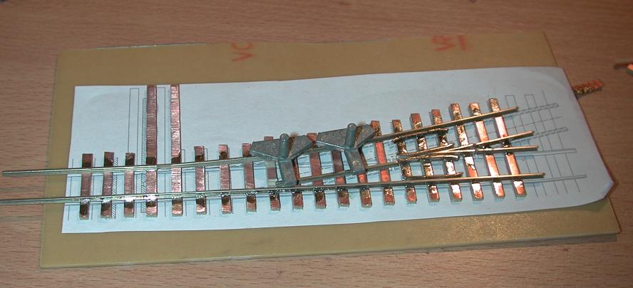
Solder the switch tabs to the heel of the point
Make sure that the rails are in line.Cut gaps into the copper foil ties
Put the turnout in warm soapy water and remove the turnout from the PCB.
Fill the gaps with filler, sand and paint the turnout.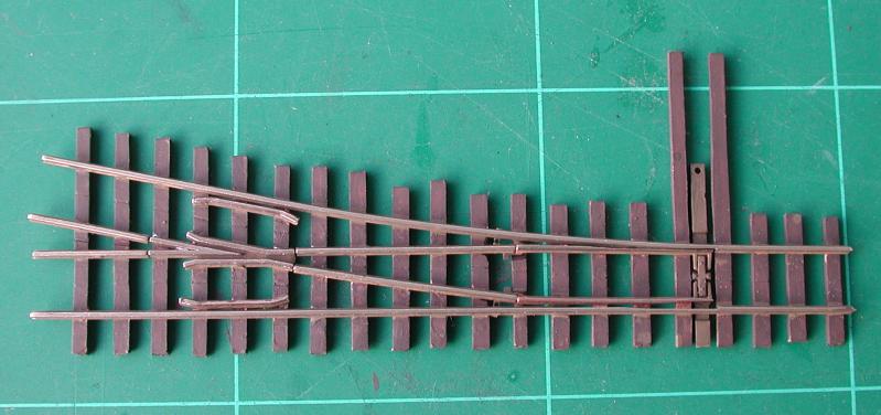
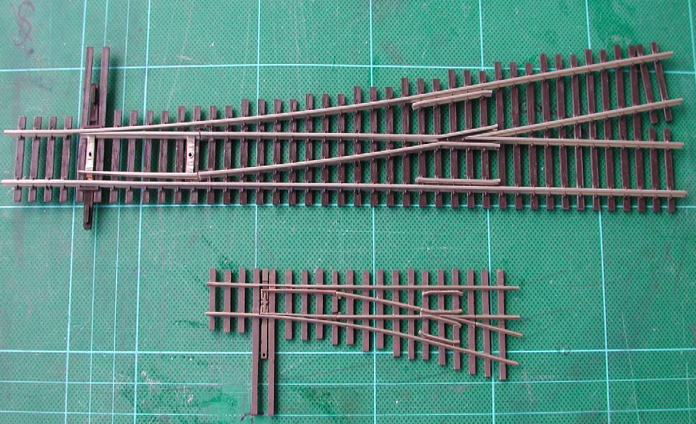
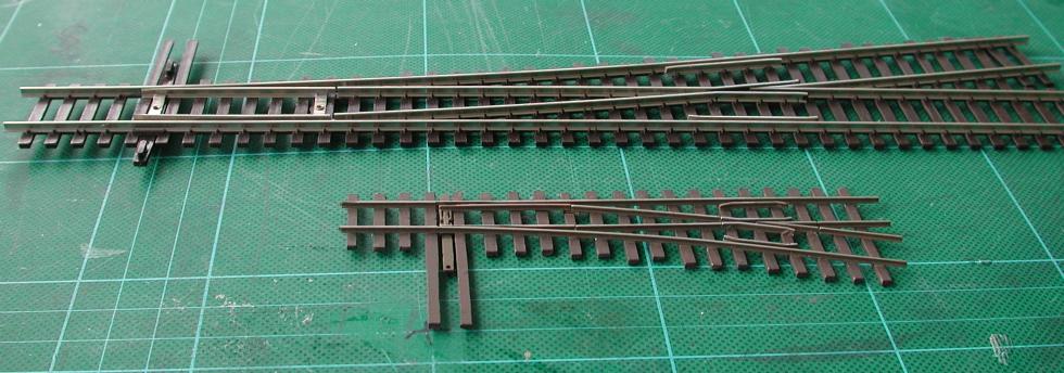
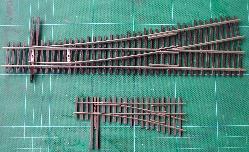
HOn30 #5 Turnout in Comparison With Shinohara HO #6 Code 100
How To Build a HO Switch with CVT Turnout Ties
There is nothing wrong with the Turnout Kits| |
 |
 |
 |
| |
 |
 |
- Notch the stock rails (I use the StockAid
 tool form Fast Tracks), notch starts about in the middle of the first head block tie
- Glue the straight stock rail to the ties
- Bend the curved stock rail till it fit to the tie plates and glue it to the ties
- File the frog point rails (I use the PointForm tool from Fast Tracks) and solder the halves together
- Glue the the frog point to the rails
- File the point rails (I use again the PointForm tool from Fast Tracks)
- File or saw a notch into the straight closure rail, bend the track (it should be parallel to the frog point rail), cut it to the length and bevel it, glue it to the ties
- Bend the curved closure rail til it fit to the tie plates
- File or saw a notch into the curved closure rail, bend the track (it should be parallel to the frog point rail), cut it to the length and bevel it, glue it to the ties
- Remove 6 plastic ties and the head tie
- Solder the PCB ties to the rails, do not solder the inside of the second switch stand tie
- Solder the throw PCB to the switch points, but not on the stock rail side
- Cut gaps to isolate the frog. I use a jewelers saw
- Cut the rail base and part of the head (but not the rail web) to build a hinge
- Solder the guard rails to the PCB ties or glue the plastic guards to the ties
- Glue the rail-braces to the ties (e.g. from Central Valley or Details West RB-920)
| |
|
 |
 |
 |
Bibliography
- Paul Mallery, Trackwork Handbook, Carstens Publishing, ISBN 911868-86-0
THE reference for trackwork. If you want to buy only one book about trackwork, you should buy this one. Subtitle Everything You Need to Learn to Know About Track - E. E. Rusel Tratman, Railway Track and Maintenance, Original printed in 1926, Kalmbach Memorial Library NMRA, ISBN 0-9647050-6-0
It's still the best way to learn from the real thing. - Kent Johnson et al, Trackwork and Lineside Detail, Kalmbach Publishing, ISBN 0-89024-71-1
The best of from Model Railroader to this topic. - Maj. W. D. Connor, Military Railways, Government Printing Office, 1917, see Georg Schreyers scannings on http://www.girr.org/girr/military_railways/military_railways.html
- J. B. Calvert, Turnouts
- Wikipedia, Railroad Switch
- Fast Tracks, Source of Quality Tools, Supplies and Information For Hand Crafted Track.


This work by Peter Schmid is licensed under a Creative Commons Attribution-ShareAlike 4.0 International License.


Topic revision: r14 - 2023-07-16 - PeterSchmid


Ideas, requests, problems regarding TWiki? Send feedback